2 Functions
188
7ST6 Manual
E50417-G1176-C251-A3
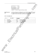
To influence information at the system interface during test mode („Test mode“ and
„Transmission block“) a CFC logic is required. Default settings already include this
logic (see Appendix).
The SIPROTEC
®
4 System Description describes in detail how to activate and deac-
tivate test mode and blocked data transmission.
Classification of In-
dications
Indications are classified as follows:
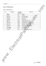
• Operational indications: indications generated while the device is operating: They
include information about the status of device functions, measurement data, system
data, and similar information.
• Fault indications: indications from the last 8 network faults that were processed by
the device.
• Indications of the Statistic: they include a counter for the switching actions of the
circuit breakers initiated by the device, maybe reclose commands as well as values
of interrupted currents and accumulated fault currents.
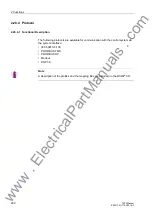
A complete list of all indication and output functions that can be generated by the
device with the maximum functional scope can be found in the Appendix. All functions
are associated with an information number (FNo). It also indicates where each indica-
tion can be sent to. If functions are not present in the specific version of the device, or
if they are set to disable, then the associated indications cannot appear.
Operational Indica-
tions (Buffer: Event
Log)
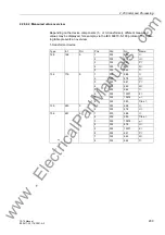
Operational indications contain information that the device generates during operation
and on operational conditions.
Up to 200 operational indications are recorded in chronological order in the device.
Newly generated indications are added to those already there. When the maximum
capacity of the memory is exhausted, the oldest indication is lost.
Operational indications come in automatically and can be read out from the device
display or a personal computer. Faults in the power system are indicated with „Net-
work Fault“ and the consecutive fault number. The fault indications contain detailed in-
formation on the behaviour of the power system fault.
Fault Indications
(Buffer: Trip Log)
Following a system fault, it is possible, for example, to retrieve important information
regarding its progress, such as pickup and trip. The start of the fault is time stamped
with the absolute time of the internal system clock. The progress of the disturbance is
output with a relative time referred to the instant of fault detection, so that the duration
of the fault until tripping and up to reset of the trip command can be ascertained. The
resolution of the time information is 1 ms.
A system fault starts with the recognition of the fault by the fault detection, i.e. first
pickup of any protection function, and ends with the reset of the fault detection, i.e.
dropout of the last protection function. Where fault causes several protective functions
to pick up, the fault is considered to include all that occurred between pickup of the
first protective function and dropout of the last protective function.
www
. ElectricalPartManuals
. com

