3 Mounting and Commissioning
230
7ST6 Manual
E50417-G1176-C251-A3
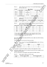
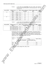
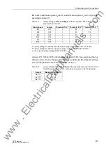
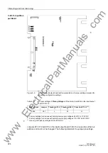
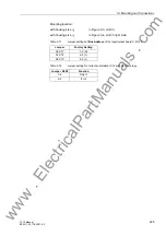
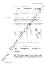
Jumper setting 1-2
: This setting makes the modem signals available, i. e. for a direct
RS232 connection between the SIPROTEC
®
0.4 device and the modem this setting
can be selected optionally. We recommend to use a standard RS232 modem connec-
tion cable (converter 9-pin to 25-pin).
Note
For a direct connection to DIGSI
®
with interface RS232 jumper X11 must be plugged
in position 2-3.
RS485 Interface
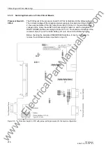
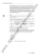
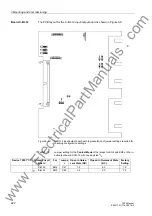
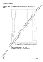
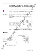
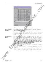
The following figure shows the location of the jumpers of interface RS485 on the inter-
face module.
Interface RS485 can be modified to interface RS232 and vice versa, according to
Figure 3-12.
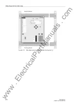
Figure 3-13
Position of matching resistors and the plug-in jumpers for configuration of the
RS485 interface
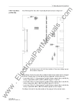
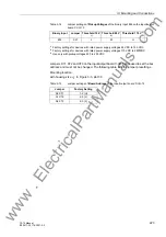
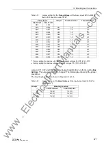
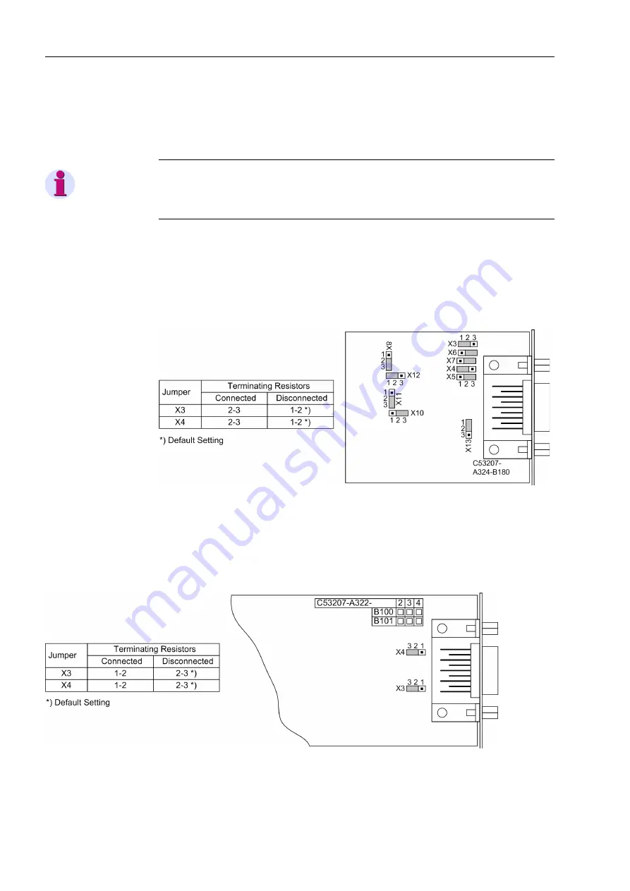
PROFIBUS Inter-
face
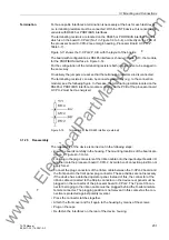
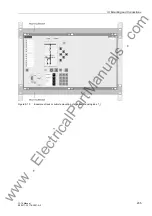
Figure 3-14
Position of the plug-in jumpers for the configuration of the terminating resistors at the interfaces PROFIBUS
(FMS and DP), DNP3.0 and Modbus
www
. ElectricalPartManuals
. com

