3 Mounting and Commissioning
232
7ST6 Manual
E50417-G1176-C251-A3
3.1.3
Mounting
3.1.3.1
Panel Flush Mounting
Depending on the version, the device housing can be
1
/
2
or
1
/
1
. For the
1
/
2
housing size
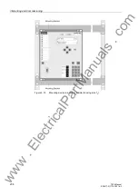
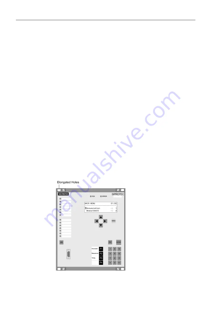
(Figure 3-16) there are four covers and four holes. For the
1
/
1
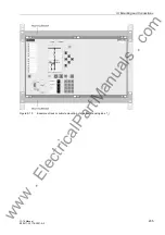
housing size (Figure 3-
17) there are six covers and six holes.
• Remove the 4 covers at the corners of the front cover, for size
1
/
1
the two covers
located centrally at the top and bottom also have to be removed. Thus the 4 respec-
tively 6 elongated holes in the mounting flange are revealed and can be accessed.
• Insert the device into the panel cut-out and fasten it with four or six screws. Dimen-
sion drawings see Section 4.17.
• Mount the four or six covers.
• Connect the low-resistance operational and protective earth on the rear plate of the
device, using at least one M4 screw for the device earthing. The cable-cross section
used must correspond to the largest connected cable cross-section, at least being
2.5 mm
2.
.
• Establish connections via the plug-in or screw connections on the rear panel of the
housing according to circuit diagram.
For screw connections with forked lugs or direct connection, before inserting wires
the screws must be tightened so that the screw heads are flush with the outer edge
of the connection block.
A ring lug must be centred in the connection chamber in such a way that the screw
thread fits in the hole of the lug.
Specifications regarding maximum cross sections, tightening torques, bending radii
and tension relief as specified in the SIPROTEC
®
4 System Description (Order No.
E50417-H1176-C151) must be observed. You will find hints in the short description
included in the device.
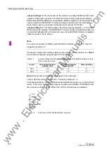
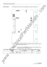
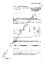
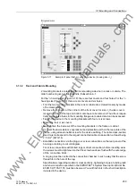
Figure 3-16
Example of panel flush mounting of a device (housing size
1
/
2
)
www
. ElectricalPartManuals
. com

