3.2 Checking Connections
237
7ST6 Manual
E50417-G1176-C251-A3
Termination
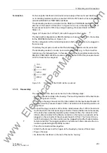
The RS485 interface is capable of half-duplex operation with signals A/A' and B/B' with
the common reference potential C/C' (GND). It is necessary to check that the termi-
nating resistors are connected to the bus only at the last unit, and not at other devices
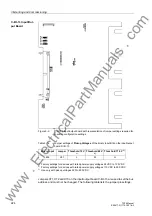
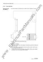
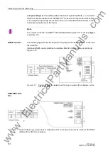
on the bus. The jumpers for the terminating resistors are on the interface module
RS485 (see Figure 3-12) or on the PROFIBUS RS485 (see Figure 3-14), or in the
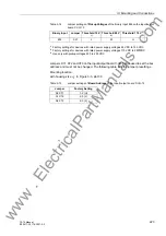
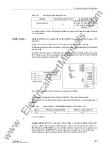
7ST6 directly on the C–CPU–2 (see Figure 3-5 and Table 3-7). Terminating resistors
can also be implemented outside the device (e.g. in the plug connectors) as shown in
Figure 3-6. In this case, the terminating resistors located on the module must be dis-
abled.
If the bus is extended, make sure again that only terminating resistors at the last
device to the bus are energized. The remaining terminating resistors at the bus may
not be energized.
Time Synchroniza-
tion Interface
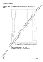
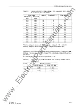
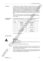
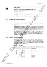
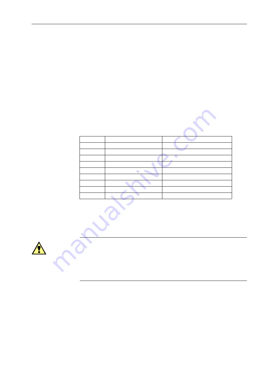
It is optionally possible to process 5 V-, 12 V- or 24 V- time synchronization signals,
provided that they are carried to the inputs named in the following table.
Table 3-23
D-subminiature connector assignment of the time synchronization interface
1)
Assigned, but cannot be used
Fibre-Optic Cables
WARNING!
Warning of laser rays!
Non-observance of the following measure can result in death, personal injury or sub-
stantial property damage.
Do not look directly into the fibre-optic elements!
The transmission via fibre optics is particularly insensitive to electromagnetic interfer-
ence and thus ensures galvanic isolation of the connection. Transmit and receive con-
nections are represented by symbols.
The normal setting of the character idle state for the fibre optic cable interface is "Light
off". If the character idle state is to be changed, use the operating program DIGSI
®
, as
described in the SIPROTEC
®
4 System Description.
Pin No.
Description
Signal Meaning
1
P24_TSIG
Input 24 V
2
P5_TSIG
Input 5 V
3
M_TSIG
Return Line
4
–
–
5
SHIELD
Shield Potential
6
–
–
7
P12_TSIG
Input 12 V
8
P_TSYNC
Input 24 V
9
SHIELD
Shield potential
www
. ElectricalPartManuals
. com

