3 Mounting and Commissioning
250
7ST6 Manual
E50417-G1176-C251-A3
3.3.8
Measuring the Operating Time of the Circuit Breaker
Only for Synchro-
nism Check
If the device is equipped with the function for synchronism and voltage check and it is
applied, it is necessary - under asynchronous system conditions - that the operating
time of the circuit breaker is measured and set correctly when closing. If the synchro-
nism check function is not used or only for closing under synchronous system condi-
tions, this subsection is irrelevant.
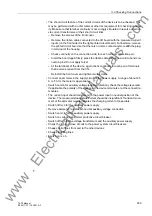
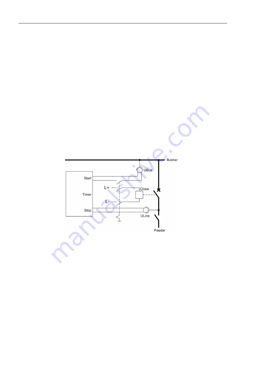
For measuring the operating time a setup as shown in Figure 3-24 is recommended.
The timer is set to a range of 1 s and a graduation of 1 ms.
The circuit breaker is connected manually. At the same time the timer is started. After
closing the poles of the circuit breaker, the voltage U
Line
appears and the timer is
stopped. The time displayed by the timer is the real circuit breaker closing time.
If the timer is not stopped due to an unfavourable closing moment, the attempt will be
repeated.
It is particularly favourable to calculate the mean value from several (3 to 5) successful
switching attempts.
Set the calculated time in address
239
as
T-CB close
(under
P.System Data 1
).
Select the next lower settable value.
Figure 3-24
Measurement of the circuit breaker closing time
3.3.9
Testing User-Defined Functions
The device has a vast capability for allowing functions to be defined by the user, es-
pecially with the CFC logic. Any special function or logic added to the device must be
checked.
Naturally, general test procedures cannot be given. Configuration of these functions
and the set value conditions must be actually known beforehand and tested. Possible
interlocking conditions of switching devices (circuit breakers, disconnectors, earth
switch) are of particular importance. They must be considered and tested.
www
. ElectricalPartManuals
. com

