2.2 Distance Protection
47
7ST6 Manual
E50417-G1176-C251-A3
2.2
Distance Protection
The type of characteristics used for the distance protection is specified in the
Functional Scope under parameter
113
DISTANCE CURVE
. Combined or polygonal
tripping characteristics are available.
2.2.1
Enabling the Distance Protection
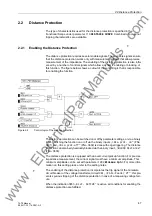
The distance protection requires several enable signals. These enable signals ensure
that the distance protection works only with measurement signals that allow precise
measurement of the impedance. The enabling of the distance protection is also influ-
enced by a number of control signals which allow a dynamic enabling or blocking of
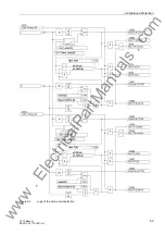
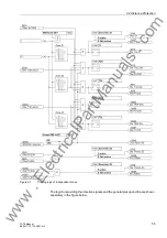
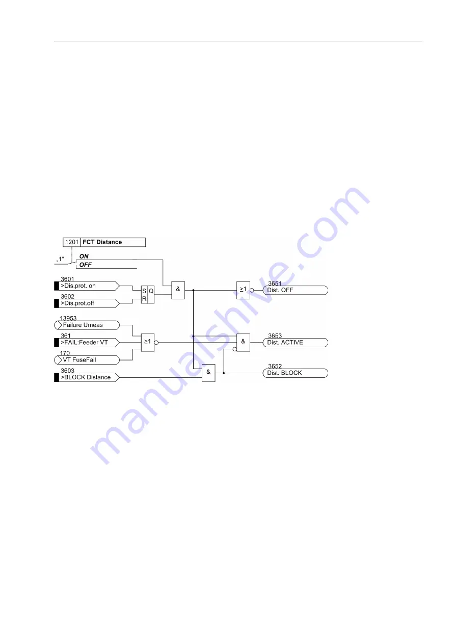
this function. The figure below shows a cutout of the control logic that is responsible
for enabling the function.
Figure 2-2
Control logic of the distance protection
The distance protection can be switched on or off by parameter settings, or via a binary
input. Switching the function on or off via the binary inputs
„>Dis.prot. on“
(FNo.
3601) and
„>Dis.prot.off“
(FNo. 3602) is done with edge triggering. The distance
protection can also be dynamically blocked via the binary input
„>BLOCK Distance“
(FNo. 3603).
The distance protection is equipped with an overcurrent pickup function. For precise
impedance measurement, the current signal must have a minimum amplitude. This
minimum amplitude can be set with parameter
1202
Minimum Iph>
. For more infor-
mation on this setting please refer to the setting notes.
The enabling of the distance protection incorporates the trip signal of the miniature
circuit breaker of the voltage transformer circuit 361
„>FAIL:Feeder VT“
; this pre-
vents spurious tripping of the distance protection in case of a measuring voltage fail-
ure.
When the indication 3653
„Dist. ACTIVE“
is active, all conditions for enabling the
distance protection are fulfilled.
www
. ElectricalPartManuals
. com

