Impedance Protection (ANSI 21)
125
7UM62 Manual
C53000-G1176-C149-3
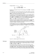
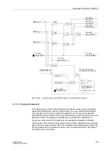
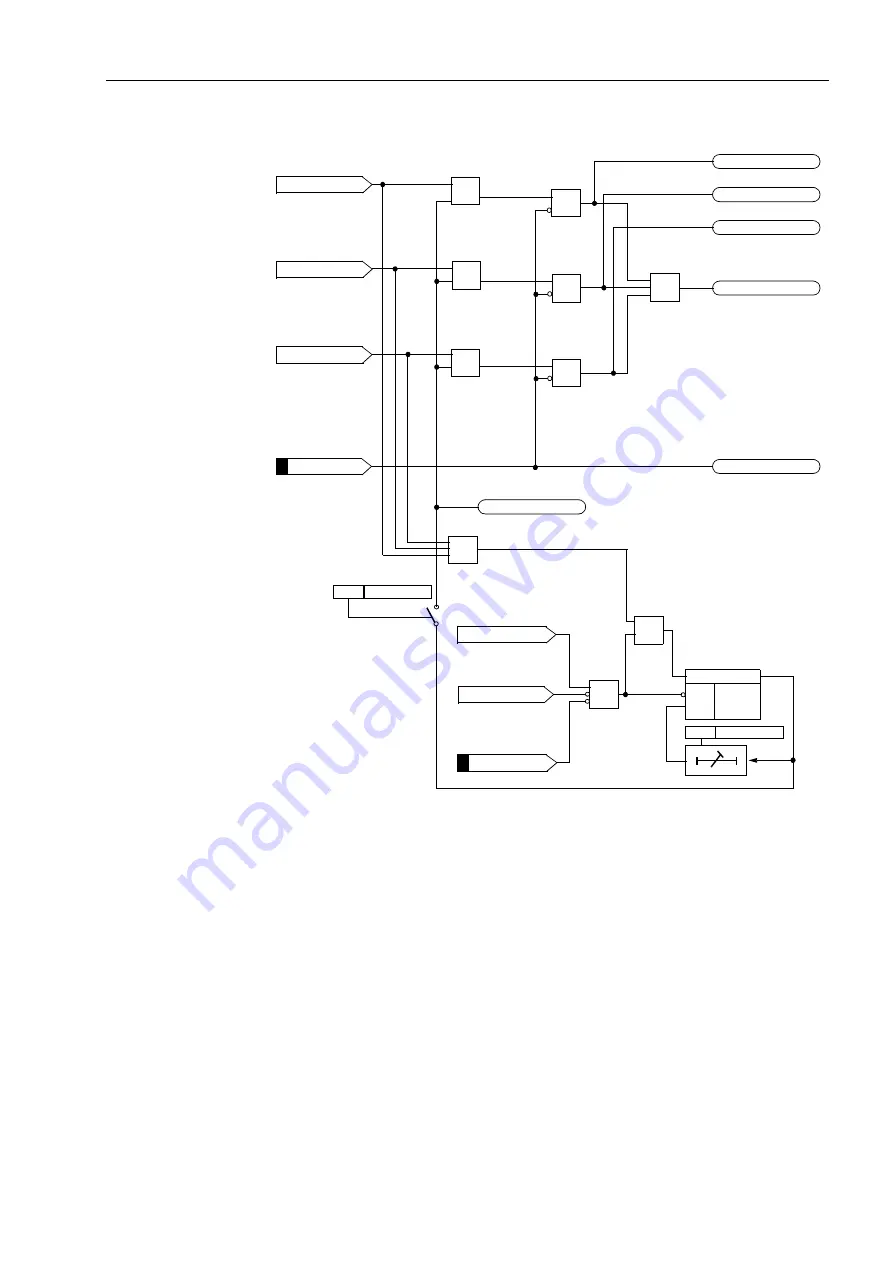
Figure 2-59
Logic Diagram of the Pickup Stage of the Impedance Protection
2.17.1.3 Tripping Characteristic
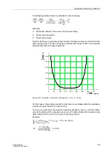
The tripping zones of the machine impedance protection relay have a polygonally
shaped trip characteristic (see also Figure 2-60). It is a symmetrical characteristic,
even though a fault in reverse direction (negative R and X values) is impossible
provided the usual connection to the current transformers at the star-point side of the
generator is used. The polygon is identified by one parameter: impedance Z.
As long as a fault detector has picked up, the impedance calculation is effected
continuously. This is carried out by complex division of the voltage and current phases
derived from the loop selection. When the calculated fault impedance lies within the
set trip characteristic, the protection issues a trip command which may be delayed
according to the time setting.
Pickup I
L1
>
Pickup I
L2
>
Pickup I
L3
>
FNo. 03953
FNo. 03966
OR
&
&
&
FNo. 03968
FNo. 03967
FNo. 03970
FNo. 03969
FNo. 03962
FNo. 03958
Pickup U1<
&
Fuse Failure
&
S
Q
R
≥
1
OR
OR
OR
OR
*)
*)
*)
seal-in logic operates
*)
separately for each phase


