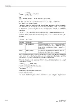
Impedance Protection (ANSI 21)
127
7UM62 Manual
C53000-G1176-C149-3
A drop-out can only be caused by a drop-out of the overcurrent pickup and not by
leaving the tripping polygon.
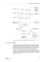
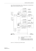
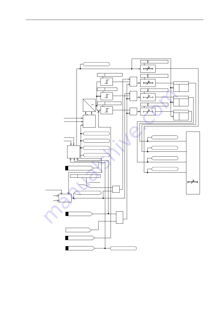
Figure 2-61 illustrates the logic diagram of the impedance protection.
Figure 2-61
Logic Diagram of the Impedance Protection
>FAIL:Feeder V
FNo. 0361
FNo. 3980
Imp.T3>TRIP
&
S
Q
R
>Extens. Z1B
FNo. 3956
>Imp. BLOCK
FNo. 3953
S
Q
R
S
Q
R
&
&
TMin
TRIP CMD
Tripping
matrix
FNo. 3978
Imp.Z1B<TRIP
FNo. 3979
Imp.Z2<TRIP
FNo. 3977
Imp.Z1<TRIP
FNo. 3970
Imp I> & U< PU
FNo. 3969
Imp. Fault L3
FNo. 3968
Imp. Fault L2
FNo. 3967
Imp. Fault L1
Loop
selection
Pickup
Z
I
L1
,I
L2
,I
L3
U
1
I
L1
,I
L2
,I
L3
U
L1
,U
L2
,U
L3
FNo. 3962
Imp. BLOCKED
U
I
OR
FNo. 3958
>Useal-in BLK
FFM
see Figure 2-120 in
Section 2.38.1.4
Power Swing
Power
swing
logic
I
2
Z
1
I
L1
, I
L2
, I
L3
Z1
Z1 and Z2
„1“
&
FNo. 03966
FNo. 3976
see Section 2.17.3


