Functions
256
7UM62 Manual
C53000-G1176-C149-3
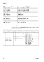
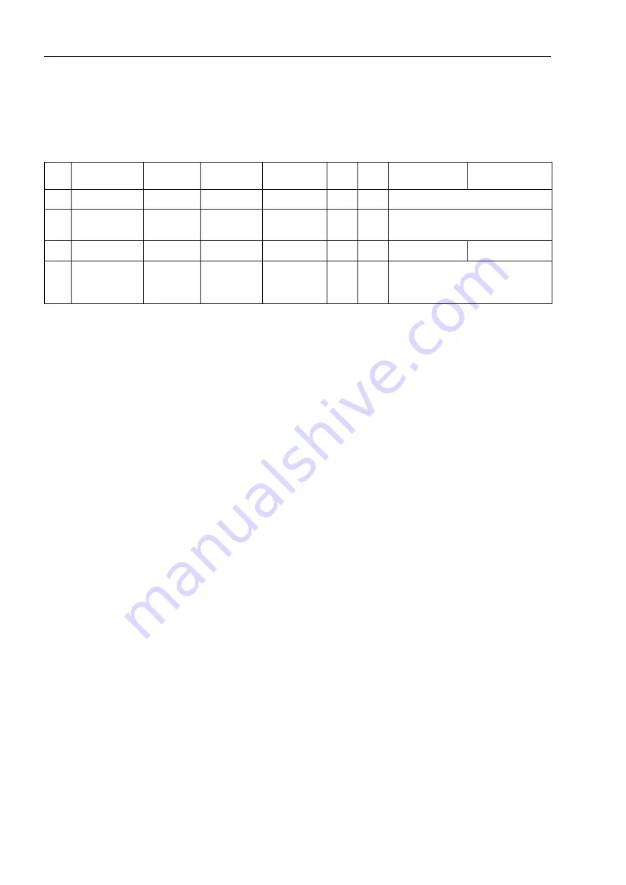
Depending on the conditions of the trip contact and the circuit breaker, the binary
inputs are activated (logical condition ”H” in Table 2-16), or not activated (logical
condition ”L”).
.
With this solution, it is impossible to distinguish between status 2 (”normal operation
with open CB LS” and ”KR triggered with success”. However, these two statuses are
normal statues and thus not critical. Status 4 is only theoretical and indicates a
hardware error. Even for healthy trip circuits the condition that both binary inputs are
not actuated (”L”) is possible during a short transition period (trip contact is closed, but
the circuit breaker has not yet opened.) A continuous state of this condition is only
possible when the trip circuit has been interrupted, a short-circuit exists in the trip
circuit, a loss of battery voltage occurs, or malfunctions occur with the circuit breaker
mechanism.
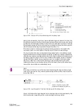
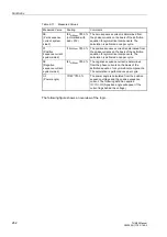
The conditions of the two binary inputs are checked periodically. A check takes place
about every 600 ms. If three consecutive conditional checks detect an abnormality
(after 1.8 s), an annunciation is reported (see Figure 2-122). The repeated
measurements help to determine the delay of the alarm message and to avoid that an
alarm is output during short-time transition phases. When the fault in the trip circuit has
been cleared, the annunciation is automatically reset.
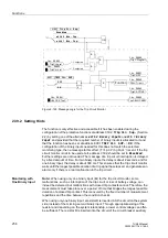
Monitoring with
One Binary Input
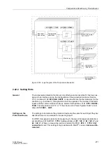
The binary input is connected according to Figure 2-124 in parallel with the associated
trip contact. The circuit breaker auxiliary contact AuxCont2 is connected in series with
a high-ohm resistor R.
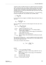
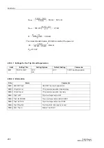
The control voltage for the circuit breaker should be about two times the value of the
minimum voltage drop at the binary (U
St
> 2 ·U
BImin
). Since the minimum voltage to
activate a binary input is 19 V, a DC voltage supply of 38 V or higher is required.
Table 2-16
Condition Table for Binary Inputs, Depending on RTC and CB Position
No.
Trip Contact
Circuit
Breaker
AuxCont 1
AuxCont 2
BI 1
BI 2
Dyn. Status
Stat. Status
1
Open
CLOSED
Closed
Open
H
L
Normal operation with closed CB
2
Open or
closed
OPEN
Open
Closed
L
H
Normal operation with open CB or
RTC has tripped with success
3
Closed
CLOSED
Closed
Open
L
L
Transition/fault
Fault
4
Open
CLOSED
or OPEN
Closed
Closed
H
H
Theoretical status: Aux. contact
defective,
BI defective, wrong connection


