Functions
18
7UM62 Manual
C53000-G1176-C149-3
2.2
Functional Scope
2.2.1
Description
General
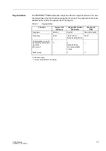
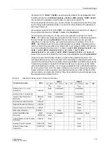
The 7UM62 has numerous protective and additional functions. The hardware and
firmware provided is designed for this scope of functions. Nevertheless a few
restrictions apply to the use of the earth fault current and earth fault voltage inputs U
E
and I
EE
respectively. It is not possible to feed different measured quantities to one and
the same input, i.e. to use the input, for example, for both rotor and stator earth fault
protection. Table 2-2 gives an overview of the protective functions and the inputs they
use.
The command functions can be matched to the plant conditions. In addition, individual
functions can be activated or deactivated during the configuration procedure, so that
functions that are not needed can be disabled.
The available protective and additional functions can be configured as
Enabled
or
Disabled
. For individual functions, the choice between several alternatives may be
presented, as described below.
Functions that are configured as
Disabled
are not processed by the 7UM62: There
are no messages, and corresponding settings (functions, limit values) are not
displayed during detailed settings.
Determination of
Functional Scope
Configuration settings may be entered using a PC and the software program DIGSI
®
4
and transferred via the operator interface on the device front, or via the rear serial
service interface. Operation is described in the SIPROTEC
®
4 System Manual.
Entry of password No. 7 (for setting modification) is required to modify configuration
settings. Without the password, the settings may be read, but cannot be modified and
transmitted to the device.
The functional scope with the available options is set in the
Device Configuration
dialog box to match plant requirements.
2.2.2
Setting Hints
Special Cases
Most settings are self-explanatory. The special cases are described below.
If the setting group change-over function is to be used, the setting in address
must be set to
enabled
. In this case, it is possible to apply two
groups of settings for the function parameters (refer also to Section 2.4) so that a
convenient and fast switch-over between these setting groups is possible. The setting
Disabled
implies that only one function parameter setting group can be applied and
used.
Note:
The functions and default settings depend of the variant ordered (for details refer to
Table 2-1 and Appendix A.1). Also, not all combinations of protective functions are
possible because of certain restrictions imposed by the hardware (see Table 2-2,
“Allocation of Device Inputs to Protection Functions”).

