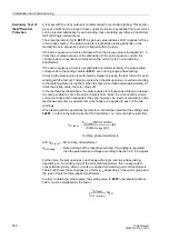
3 Installation and Commissioning
326
7UM62 Manual
C53000-G1176-C149-3
In the version 7UM622, the contact type can be changed for one specific relay (BO13)
from normally open to normally closed (see overview diagrams in section A.2 of the
Appendix).
1
) Factory settings for devices with power supply voltages of 24 VDC to 125 VDC.
2
) Factory settings for devices with power supply voltages of 110 VDC to 220 VDC and 115 VAC.
Bus Address
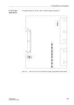
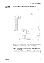
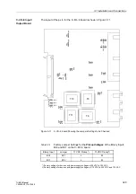
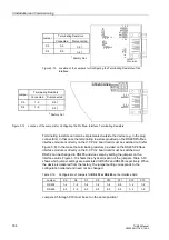
Jumpers X71, X72 and X73 on the I/O-1 board are used to set the bus address and
must not be changed. Table 3-9 shows the factory setting of the jumpers. The physical
location of the modules is shown in Figures 3-5 and 3-6.
Table 3-7
Jumper Settings for the Contact of Relay R13 (Binary Output BO 13)
Jumper
Non-Energized Position Open
(NO Contact)
Non-Energized Position Closed
(NC Contact)
Factory Setting
X40
1–2
2–3
1–2
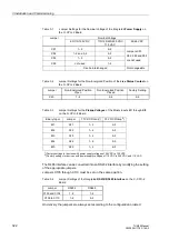
Table 3-8
Factory Jumper Settings for the Pickup Voltages of the Binary Inputs
BI 8 through BI 15 on the C–I/O–1 board of the 7UM622
Binary Input
Jumper
17 VDC Pickup
1
)
73 VDC Pickup
2
)
BI 8
X21/X22
L
M
BI 9
X23/X24
L
M
BI 10
X25/X26
L
M
BI 11
X27/X28
L
M
BI 12
X29/X30
L
M
BI 13
X31/X32
L
M
BI 14
X33/X34
L
M
BI 15
X35/X36
L
M
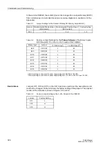
Table 3-9
Factory Jumper Setting on the C–I/O–1 Board of the 7UM622
Jumper
Factory Setting
X71
L
X72
H
X73
H

