3.2 Checking Connections and System (Plant) Integration
339
7UM62 Manual
C53000-G1176-C149-3
o
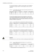
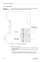
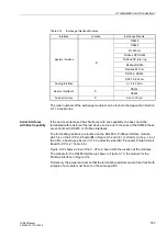
Close the protective switches to apply voltage to the power supply. Check the polarity
and magnitude of the voltage at the device terminals or at the connector modules.
Visual Inspection
Check the cubicle and the devices for damage, condition of the connections etc., and
device earthing.
Secondary Testing
This test does not undertake to check the individual protection functions for the
accuracy of their pick-up values and characteristic curves. Unlike analog electronic or
electromechanical protective devices, no protection function test is required within the
framework of the device test, since this is ensured by the factory tests. Protection
functions are only used to check the device connections.
A plausibility check of the analog-digital converter with the operational measured
values is sufficient since the subsequent processing of the measured values is
numerical and thus internal failures of protection functions can be ruled out.
Where secondary tests are to be performed, a three-phase test equipment providing
test currents and voltages is recommended (e.g. Omicron CMC 56 for manual and
automatic testing). The phase angle between currents and voltages should be
continuously controllable.
The accuracy which can be achieved during testing depends on the accuracy of the
testing equipment. The accuracy values specified in the Technical data can only be
reproduced under the reference conditions set down in IEC 60 255 resp. VDE 0435/
part 303 and with the use of precision measuring instruments.
Tests can be performed using the currently set values or the default values.
If unsymmetrical currents and voltages occur during the tests it is likely that the
asymmetry monitoring will frequently operate. This is of no concern because the
condition of steady-state measured values is monitored and, under normal operating
conditions, these are symmetrical; under short circuit conditions these monitoring
systems are not effective.
Note:
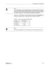
If a redundant supply is used, there must be a permanent, i.e. uninterruptible
connection between the minus polarity connectors of system 1 and system 2 of the
d.c. voltage supply (no switching device, no fuse), because otherwise there is a risk
of voltage doubling in case of a double earth fault.
Note: During dynamic testing, at least one a.c. measured quantity should be present
at one of the analog inputs, with a sufficient amplitude.
The measured quantities of the earth paths (I
EE
, U
E
) cannot be used for the integrated
sampling frequency adaptation. During tests concerning I
EE
or U
E
, at least one a.c.
measured quantity must be applied to one of the phase inputs.

