A Appendix
502
7UM62 Manual
C53000-G1176-C149-3
A.6
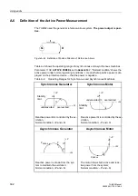
Definition of the Active Power Measurement
The 7UM62 used the generator reference-arrow system. The power output is posi-
tive.
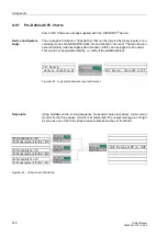
Figure A-44 Definition of Positive Direction of Reference Arrows
Table A-2 shows the operating ranges for synchronous and asynchronous machines.
Parameter
is set to
Generator
. “Normal condition” shows the
active power under normal operating conditions: + means that a positive power is dis-
played on the protective device, – that the power is negative.
Table A-2
Operating Ranges for Synchronous and Asynchronous Machines
Synchronous Generator
Synchronous Motor
Asynchronous Generator
Asynchronous Motor
I
U
G
ϕ
+P
+Q
I
U
Stability
limit
underexcited
overexcited
Reactive power Q is controlled by the ex-
citation,
Normal condition: +P and +Q
+P
+Q
I
U
Stability
limit
underexcited
overexcited
Reactive power Q is controlled by the ex-
citation,
Normal condition: –P and +Q
ϕ
ϕ
+P
+Q
I
U
Reactive power is drawn from the sys-
tem to maintain the excitation;
Normal condition: +P and –Q
P
BREAK
P
ϕ
+P
+Q
I
U
The motor draws both active and reac-
tive power from the system;
Normal condition: –P and –Q
P
BREAK
P


