Definite-Time Overcurrent Protection (I>, ANSI 50/51) with Undervoltage Seal-In
39
7UM62 Manual
C53000-G1176-C149-3
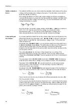
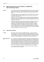
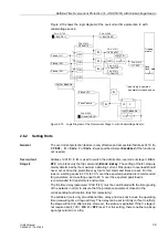
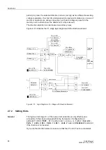
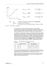
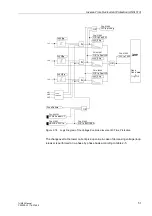
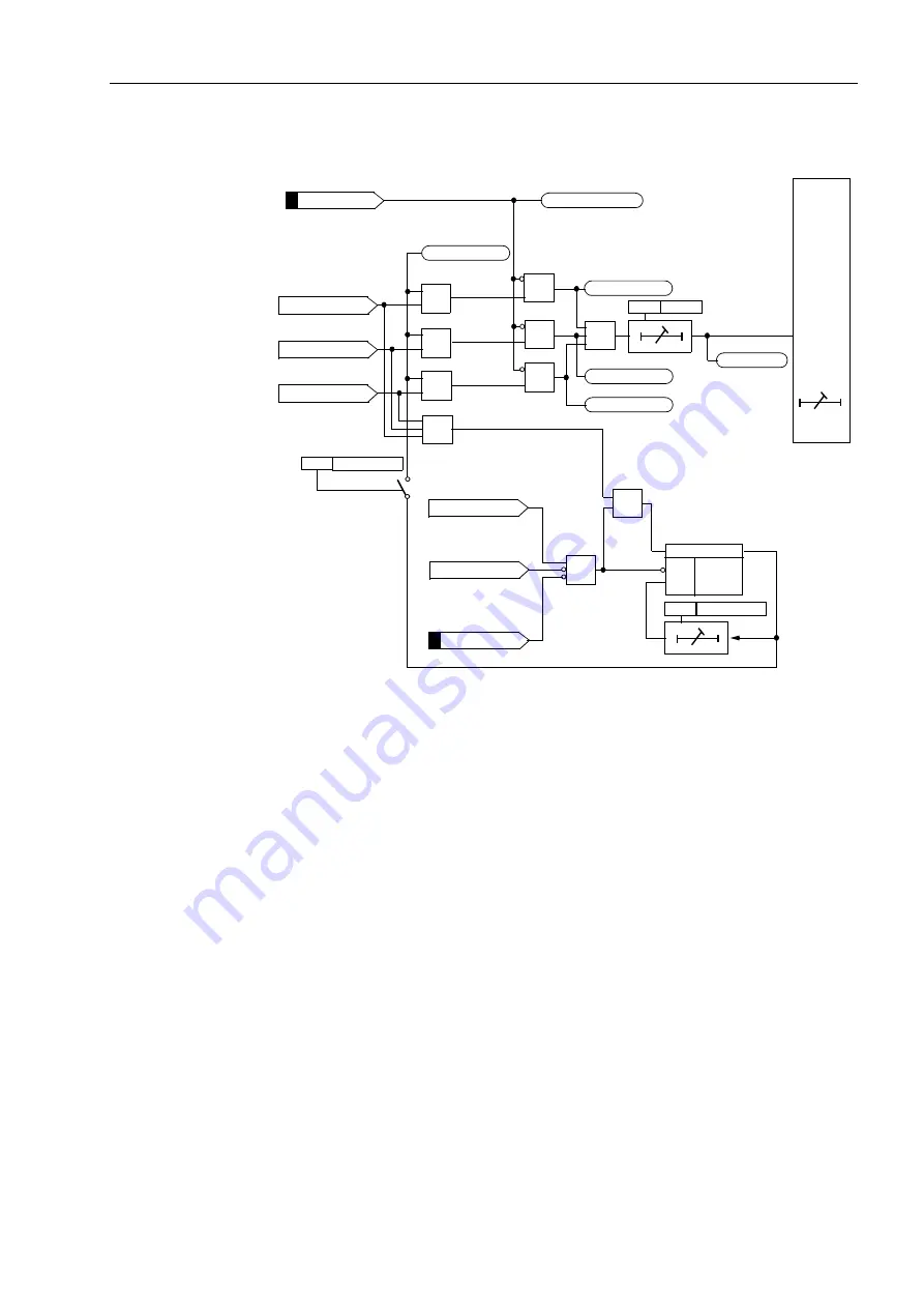
Figure 2-10 shows the logic diagram of the overcurrent time protection I> with
undervoltage seal-in.
Figure 2-10
Logic Diagram of the Overcurrent Stage I> with Undervoltage Seal-In
2.6.2
Setting Hints
General
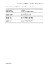
The overcurrent protection feature is only effective and accessible if address
=
Side 1
or
Side 2
was specified. Select
Disabled
if the function is
not needed.
Overcurrent
Stage I>
Address
is used to switch the definite time-overcurrent stage I>
ON
or
OFF
, or to block only the trip command (
Block Relay
. The setting of the
stage is
mainly determined by the maximum operating current. Pickup due to overload should
never occur since the protection may trip if short command times are set. For this
reason, a setting equal to 20 % to 30 % over the expected peak load is recommended
for generators, and a setting equal to 40 % over the expected peak load is
recommended for transformers and motors.
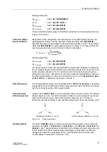
The trip time delay (parameter
) must be coordinated with the time grading
of the network in order to ensure that the protective equipment closest to the
corresponding fault location trips first (selectivity).
The settable time is only an additional time delay and does not include the operating
time (measuring time, drop-out time). The delay can be set to infinity
∞
. If set to infinity,
the stage will not trip after pickup. However, the pickup is signalled. If the I> stage is
not required at all,
O/C I> =
OFF
is set. For this setting, there is neither a pickup
signal generated nor a trip.
FNo. 01966
FNo. 01722
Pickup IL1>
Tripping
matrix
Pickup IL3>
Pickup IL2>
&
FNo. 01970
&
&
FNo. 01811
FNo. 01812
FNo. 01813
FNo. 01815
FNo. 01950
Pickup U1<
&
Fuse Failure
&
S
Q
R
≥
1
OR
OR
OR
OR
OR
TMin
TRIP CMD
seal-in logic operates
*)
*)
*)
*)
separately for each phase

