2.2 Differential Protection
113
7UT613/63x Manual
C53000-G1176-C160-2
A dropout is detected when, during 2 cycles, pick-up is no longer recognised in the dif-
ferential value, i.e. the differential current has fallen below 70 % of the set value, and
the other pickup conditions are no longer fulfilled either.
If a trip command has not been initiated, the fault is considered ended on dropout.
If a trip command had been initiated, it is maintained for the minimum command dura-
tion set in the general device data for all protection functions (see also 2.1.4). The trip
command will not be reset until all other dropout conditions mentioned above are ful-
filled as well.
2.2.2
Differential Protection for Transformers
Matching of the
Measured Values
In power transformers, generally, the secondary currents of the current transformers
are not equal when a current flows through the power transformer, but depend on the
transformation ratio and the connection group of the protected power transformer, and
the rated currents of the current transformers. The currents must therefore be
matched in order to become comparable.
Matching to the various power transformer and current transformer ratios and of the
phase displacement according to the vector group of the protected transformer is per-
formed purely mathematically. As a rule, external matching transformers are not re-
quired.
The input currents are converted in relation to the power transformer rated currents.
This is achieved by entering the rated transformer data, such as rated power, rated
voltage and rated primary currents of the current transformers, into the protection
device (Subsection „General Power System Data“ under margin heading „Object Data
with Transformers“, and „Current Transformer Data for 3-phase Measuring Loca-
tions“).
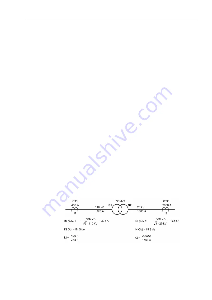
Figure 2-26 shows an example of magnitude matching. The primary nominal currents
of the two sides (windings) S1 (378 A) and S2 (1663 A) are calculated from the rated
apparent power of the transformer (72 MVA) and the nominal voltages of the windings
(110 kV and 25 kV). Since the nominal currents of the current transformers deviate
from the nominal currents of the power transformer sides, the secondary currents are
multiplied with the factors k1 and k2. After this matching, equal current magnitudes are
achieved at both sides under nominal conditions of the power transformer.
Figure 2-26
Magnitude matching — example of a two-winding power transformer (phase re-
lation not considered)
Summary of Contents for SIPROTEC 7UT613 series
Page 16: ...Contents 16 7UT613 63x Manual C53000 G1176 C160 2 Literature 631 Glossary 623 Index 633 ...
Page 30: ...1 Introduction 30 7UT613 63x Manual C53000 G1176 C160 2 ...
Page 506: ...A Appendix 506 7UT613 63x Manual C53000 G1176 C160 2 7UT633 D E ...
Page 508: ...A Appendix 508 7UT613 63x Manual C53000 G1176 C160 2 7UT633 P Q ...
Page 510: ...A Appendix 510 7UT613 63x Manual C53000 G1176 C160 2 7UT635 D E ...
Page 512: ...A Appendix 512 7UT613 63x Manual C53000 G1176 C160 2 7UT635 P Q ...
Page 515: ...A 2 Terminal Assignments 515 7UT613 63x Manual C53000 G1176 C160 2 7UT633 B ...
Page 517: ...A 2 Terminal Assignments 517 7UT613 63x Manual C53000 G1176 C160 2 7UT633 N ...
Page 519: ...A 2 Terminal Assignments 519 7UT613 63x Manual C53000 G1176 C160 2 7UT635 B ...
Page 521: ...A 2 Terminal Assignments 521 7UT613 63x Manual C53000 G1176 C160 2 7UT635 N ...
Page 622: ...A Appendix 622 7UT613 63x Manual C53000 G1176 C160 2 ...
Page 632: ...Literature 632 7UT613 63x Manual C53000 G1176 C160 2 ...


