Functions
2.7 Monitoring Function
SIPROTEC, 7VK61, Manual
C53000-G1176-C159-3, Release date 05.2009
135
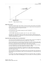
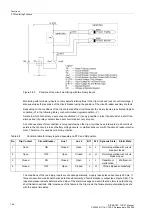
Figure 2-47
Voltage symmetry monitoring
Voltage Phase Sequence
Verification of the faulted phases, phase preference, direction measurement and polarisation with quadrature
voltages usually require clockwise rotation of the measured values. The phase rotation of the measured volt-
ages is checked by monitoring the voltage phase sequence
U
L1
before U
L2
before U
L3
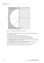
This check takes place if each measured voltage has a minimum magnitude of
|U
L1
|, |U
L2
|, |U
L3
| > 40 V/
√
3
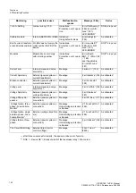
. In case of negative phase rotation, the indication
„Fail Ph. Seq.“
(No. 171) is issued.
If the system has a negative phase rotation, this must have been set during the configuration of the power
system data (refer to Section 2.1.3.1, address
235
). In such event, the phase rotation monitoring applies to the
corresponding opposite phase sequence.
Asymmetrical Measuring Voltage Failure "Fuse Failure Monitor".
In the event of a measured voltage failure due to a short circuit fault or a broken conductor in the voltage trans-
former secondary circuit certain measuring loops may mistakenly see a voltage of zero.
If fuses are used instead of a secondary miniature circuit breaker (VT mcb) with connected auxiliary contacts,
then the („Fuse Failure Monitor“) can detect problems in the voltage transformer secondary circuit. Of course,
the miniature circuit breaker and the „Fuse Failure Monitor“ can be used at the same time.
The „Fuse-Failure-Monitor“ is only active if the three-phase currents and voltages are connected. Otherwise,
this function is disabled and the associated parameters and indications are hidden .
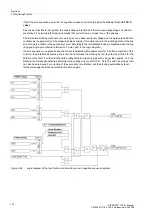
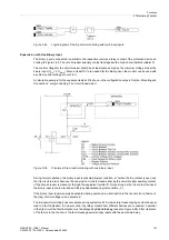
The asymmetrical measured voltage failure is characterized by its voltage asymmetry with simultaneous
current symmetry. Figure 2-48 shows the logic diagram of the „Fuse Failure Monitor“ during asymmetrical
failure of the measured voltage.
If there is substantial voltage asymmetry of the measured values, without asymmetry of the currents being reg-
istered at the same time, this indicates the presence of an asymmetrical failure in the voltage transformer sec-
ondary circuit.
The asymmetry of the voltage is detected by the fact that either the zero sequence voltage or the negative se-
quence voltage exceed a settable value
FFM U>(min)
. The current is assumed to be sufficiently symmetrical
Summary of Contents for Siprotec 7VK61
Page 8: ...Preface SIPROTEC 7VK61 Manual C53000 G1176 C159 3 Release date 05 2009 8 ...
Page 14: ...Contents SIPROTEC 7VK61 Manual C53000 G1176 C159 3 Release date 05 2009 14 ...
Page 316: ...Literature SIPROTEC 7VK61 Manual C53000 G1176 C159 3 Release date 05 2009 316 ...
Page 328: ...Glossary SIPROTEC 7VK61 Manual C53000 G1176 C159 3 Release date 05 2009 328 ...


