Functions
2.10 Command Processing
SIPROTEC, 7VK61, Manual
C53000-G1176-C159-3, Release date 05.2009
173
2.10.1.3 Interlocking
Interlocking can be executed by the user-defined logic (CFC). Switchgear interlocking checks in a SI-
CAM/SIPROTEC 4 system are normally divided in the following groups:
• System interlocking checked by a central control system (for interbay interlocking),
• Zone controlled / bay interlocking checked in the bay device (for the feeder).
• Cross-bay interlocking via GOOSE messages directly between bay controllers and protection relays (with
rollout of IEC 61850; inter-relay communication by GOOSE is performed via the EN100 module)
System interlocking is based on the process image in the central device. Zone controlled / bay interlocking
relies on the object database (feedback information) of the bay unit (here the SIPROTEC 4 relay) as was de-
termined during configuration (see SIPROTEC 4 System Description).
The extent of the interlocking checks is determined by the configuration and interlocking logic of the relay. For
more information on GOOSE, please refer to the SIPROTEC 4 System Description.
Switching objects that require system interlocking in a central control system are marked by a specific param-
eter inside the bay unit (via configuration matrix).
For all commands, operation with interlocking (normal mode) or without interlocking (test mode) can be select-
ed:
• For local commands by reprogramming the settings with password check,
• For automatic commands, via command processing by CFC and Deactivated Interlocking Recognition,
• For local / remote commands, using an additional interlocking disable command via PROFIBUS.
Interlocked/non-interlocked Switching
The configurable command checks in the SIPROTEC 4 devices are also called „standard interlocking“. These
checks can be activated via DIGSI (interlocked switching/tagging) or deactivated (non-interlocked).
De-interlocked or non-interlocked switching means that the configured interlock conditions are not tested.
Interlocked switching means that all configured interlocking conditions are checked within the command pro-
cessing. If a condition could not be fulfilled, the command will be rejected by an indication with a minus added
to it, e.g. „CO–“, followed by an operation response information. The command is rejected if a synchronism
check is carried out before closing and the conditions for synchronism are not fulfilled. Table 2-10 shows some
types of commands and indications. The indications marked with *) are displayed only in the event logs on the
device display; for DIGSI they appear in spontaneous indications.
Table 2-10
Command types and corresponding indications
The plus sign indicated in the message is a confirmation of the command execution: The command output has
a positive result, as expected. A minus sign means a negative, i.e. an unexpected result; the command was
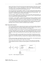
rejected. Figure 2-71 shows an example in the operational indications command and feedback of a positively
run switching action of the circuit breaker.
The check of interlocking can be programmed separately for all switching devices and tags that were set with
a tagging command. Other internal commands such as overriding or abort are not tested, i.e. are executed in-
dependently of the interlockings.
Type of Command
Control
Cause
Indication
Control issued
Switching
CO
CO+/–
Manual tagging (positive / negative)
Manual tagging
MT
MT+/–
Information state command, Input blocking
Input blocking
ST
ST+/– *)
Information state command, Output blocking
Output blocking
ST
ST+/– *)
Cancel command
Cancel
CA
CA+/–
Summary of Contents for Siprotec 7VK61
Page 8: ...Preface SIPROTEC 7VK61 Manual C53000 G1176 C159 3 Release date 05 2009 8 ...
Page 14: ...Contents SIPROTEC 7VK61 Manual C53000 G1176 C159 3 Release date 05 2009 14 ...
Page 316: ...Literature SIPROTEC 7VK61 Manual C53000 G1176 C159 3 Release date 05 2009 316 ...
Page 328: ...Glossary SIPROTEC 7VK61 Manual C53000 G1176 C159 3 Release date 05 2009 328 ...

