Mounting and Commissioning
3.1 Mounting and Connections
SIPROTEC, 7VK61, Manual
C53000-G1176-C159-3, Release date 05.2009
185
Note
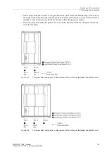
If binary inputs are used for trip circuit supervision, note that two binary inputs (or a binary input and a substitute
resistor) are connected in series. The switching threshold must lie clearly below half of the nominal control volt-
age.
Type of Contact for Output Relays
Input/output boards can have relays that are equipped with changeover contacts. For this it is necessary to alter
a jumper. The following sections at „Switching Elements on Printed Circuit Boards“ explain for which relays on
which boards this applies.
Exchanging Interfaces
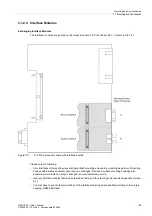
Only serial interfaces of devices for panel and cubicle mounting as well as of mounting devices are replaceable.
Which interfaces can be exchanged, and how this is done, is described in the following section under the side
title „Exchanging Interface Modules“.
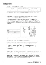
Terminating interfaces with bus capability
If the device is equipped with a serial RS485 port, the RS485 bus must be terminated with resistors at the last
device on the bus to ensure reliable data transmission. For this purpose termination resistors are provided on
the PCB of the C-CPU-2 processor board and on the RS485 or PROFIBUS/DNP interface module which can
be connected via jumpers. The spatial arrangement of the jumpers on the PCB of the processor module C-
CPU-2 is described in the following sections under „Processor module C-CPU-2“ and on the interface modules
under „RS485 interface“ and „PROFIBUS interface“. Both jumpers must always be plugged in the same way.
The termination resistors are disabled on delivery.
Spare Parts
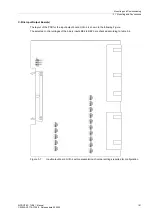
Spare parts can be the battery for storage of data in the battery-buffered RAM in case of a power failure, and
the internal power supply miniature fuse. Their spatial arrangement is shown in the figure of the processor
board. The ratings of the fuse are printed on the board next to the fuse itself. When replacing the fuse, please
observe the guidelines given in the SIPROTEC 4 System Description in the chapter „Maintenance“ and „Cor-
rective Maintenance“.
Summary of Contents for Siprotec 7VK61
Page 8: ...Preface SIPROTEC 7VK61 Manual C53000 G1176 C159 3 Release date 05 2009 8 ...
Page 14: ...Contents SIPROTEC 7VK61 Manual C53000 G1176 C159 3 Release date 05 2009 14 ...
Page 316: ...Literature SIPROTEC 7VK61 Manual C53000 G1176 C159 3 Release date 05 2009 316 ...
Page 328: ...Glossary SIPROTEC 7VK61 Manual C53000 G1176 C159 3 Release date 05 2009 328 ...

