Mounting and Commissioning
3.3 Commissioning
SIPROTEC, 7VK61, Manual
C53000-G1176-C159-3, Release date 05.2009
222
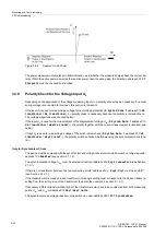
Figure 3-24
Apparent Load Power
The power measurement provides an initial indication as to whether the measured values have the correct po-
larity. If both the active power as well as the reactive power have the wrong sign, the polarity in address
201
CT
Starpoint
must be checked and rectified.
3.3.8
Polarity Check for the Voltage Input U
4
Depending on the application of the voltage measuring input U
4
, a polarity check may be necessary. If no mea-
suring voltage is connected to this input, this section is irrelevant.
If the input U
4
is used for measuring a voltage for overvoltage protection (
P.System Data 1
address
210
U4
transformer
=
Ux transformer
), no polarity check is necessary because the polarity is irrelevant here.
The voltage magnitude was checked before.
If the input U
4
is used for the measurement of the displacement voltage U
en
(
P.System Data 1
address
210
U4 transformer
=
Udelta transf.
), the polarity together with the current measurement is checked (see
below).
If input U
4
is used for measuring a voltage of the synchronism check (
P.System Data 1
address
210
U4
transformer
=
Usy2 transf.
), the polarity must be checked as follows using the synchronism check func-
tion:
Only for Synchronism Check
The device must be equipped with the synchronism and voltage check function which must be configured under
address
135
Enabled
(see section 2.1.1.2).
The synchronisation voltage U
sy2
must be entered correctly at address
212
Usy2 connection
(see Section
2.1.3.1).
If there is no transformer between the two measuring points, address
214
ϕ
Usy2-Usy1
must be set to
0
°
(see Section 2.1.3.1).
If the measurement is made across a transformer, this angle setting must correspond to the phase rotation re-
sulting from the vector group of the transformer (see also the example in section 2.1.3.1).
If necessary, different transformation ratios of the transformers may have to be considered from both measuring
points U
sy1
and U
sy2
at address
215
Usy1/Usy2 ratio
.
The synchronism and voltage check must be switched under address
3501
FCT Synchronism
.
Summary of Contents for Siprotec 7VK61
Page 8: ...Preface SIPROTEC 7VK61 Manual C53000 G1176 C159 3 Release date 05 2009 8 ...
Page 14: ...Contents SIPROTEC 7VK61 Manual C53000 G1176 C159 3 Release date 05 2009 14 ...
Page 316: ...Literature SIPROTEC 7VK61 Manual C53000 G1176 C159 3 Release date 05 2009 316 ...
Page 328: ...Glossary SIPROTEC 7VK61 Manual C53000 G1176 C159 3 Release date 05 2009 328 ...


