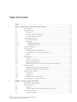
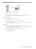
background image

Connection Examples

[dw_7xr81 connection examples, 1, en_US]
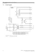
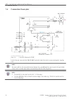
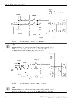
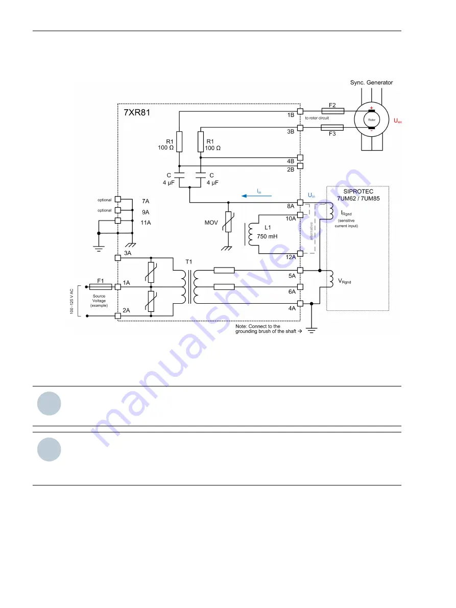
Figure 1-6

Connection Example for 7XR81

Refer to the user manual of the 7UM62/7UM85 protection relay for details on commissioning the coupling
unit.

i

i

NOTE

The inductor L1 can be connected in series between the output 8A and the input current of the protection
relay in order to reduce high ripple noise injected by some excitation regulators.

i

i

NOTE

The fuse F1 must be rated for 250 V AC, 1 A T (time-lag).

The fuses F2/F3 must have at least the rated voltage of excitation (e.g. 1000 V DC) and be rated for
0.6 A T (time-lag).

1.4

7XR81 – Coupling Device for Rotor Ground-Fault Protection
1.4 Connection Examples

18

SIPROTEC, Coupling Units for Generator Protection, Manual

C53000-H5040-C072-1, Edition 09.2018

Summary of Contents for SIPROTEC 7XR8004

Page 1: ...04 Manual C53000 H5040 C072 1 Preface Table of Contents 7XR81 Coupling Device for Rotor Ground Fault Protection 1 7XR8004 Resistor Coupling Unit for 7XT71 2 7XR86 Voltage Divider 5 1 5 2 3 7XR87 Voltage Divider for Excitation Voltage 4 Commissioning and Maintenance A Index ...

Page 2: ...ct or of business relations nor does it change these All obligations of Siemens AG are stated in the relevant contractual agree ments Siemens AG reserves the right to revise this document from time to time Document version C53000 H5040 C072 1 01 Edition 09 2018 Version of the product described Copyright Copyright Siemens AG 2018 All rights reserved The disclosure duplication distribution and editi...

Page 3: ...s relating to electromagnetic compatibility EMC Directive 2014 30 EU 7XR86 7XR81 7XR8004 7XR87 and concerning electrical equipment for use within specified voltage limits Low Voltage Directive 2014 35 EU 7XR86 7XR81 This conformity is based on the compliance with the following harmonized standards EN 60255 27 EN 60255 26 EN 50581 RoHS directive 2011 65 EU is met using the standard EN 50581 7XR86 7...

Page 4: ...UTION CAUTION means that medium severe or slight injuries can occur if the specified measures are not taken Comply with all instructions in order to avoid moderate or minor injuries NOTICE NOTICE means that property damage can result if the measures specified are not taken Comply with all instructions in order to avoid property damage i i NOTE Important information about the product product handli...

Page 5: ...erty damage can result The equipment must be grounded at the grounding terminal before any connections are made All circuit components connected to the power supply may be subject to dangerous voltage Hazardous voltages may be present in equipment even after the supply voltage has been disconnected capacitors can still be charged Operation of equipment with exposed current transformer circuits is ...

Page 6: ...6 SIPROTEC Coupling Units for Generator Protection Manual C53000 H5040 C072 1 Edition 09 2018 ...

Page 7: ...ndards 20 1 6 2 Installation Requirements 20 1 6 3 Insulation and Safety Tests 20 1 6 4 EMC Immunity Tests Type Tests Test under Mounting Conditions 20 1 7 Mechanical Tests 21 1 7 1 Vibration and Shock Stress in Stationary Use 21 1 7 2 Vibration and Shock Stress during Transport 21 1 8 Environmental Conditions 22 1 8 1 Temperatures 22 1 8 2 Humidity 22 1 8 3 Other Environmental Information 22 1 9 ...

Page 8: ...ies 40 3 3 1 Mechanical Structure 40 3 3 2 Dimensions 40 3 3 2 1 Panel Surface Mounting 40 3 4 Technical Data 41 3 4 1 Load Capability of the Voltage Divider 41 3 4 2 Weight 41 3 5 Electrical Tests 42 3 5 1 Standards 42 3 5 2 Installation Requirements 42 3 5 3 Insulation and Safety Tests 42 3 5 4 EMC Immunity Tests Type Tests Test under Mounting Conditions 42 3 6 Mechanical Tests 43 3 7 Environmen...

Page 9: ...mmunity Tests Type Tests Test under Mounting Conditions 56 4 6 Mechanical Tests 57 4 7 Environmental Conditions 58 4 7 1 Temperatures 58 4 7 2 Humidity 58 4 7 3 Other Environmental Information 58 4 8 Protection Degree according to IEC 60529 59 A Commissioning and Maintenance 61 A 1 Unpacking a Device 62 A 2 Commissioning 63 A 3 Storing a Device 64 A 4 Repacking a Device 65 A 5 Returning a Device 6...

Page 10: ...10 SIPROTEC Coupling Units for Generator Protection Manual C53000 H5040 C072 1 Edition 09 2018 ...

Page 11: ...3 Construction Properties 15 1 4 Connection Examples 18 1 5 Technical Data 19 1 6 Electrical Tests 20 1 7 Mechanical Tests 21 1 8 Environmental Conditions 22 1 9 Protection Degree according to IEC 60529 23 Ordering Information Use the following table for ordering the device Order No MLFB Pos 1 2 3 4 5 6 7 8 9 10 11 12 7 X R 8 1 0 0 0 A 0 0 Housing Panel surface mounting housing with screw terminal...

Page 12: ...k diagram 1 en_US Figure 1 1 Block Diagram of the 7XR81 1 1 7XR81 Coupling Device for Rotor Ground Fault Protection 1 1 Block Diagram 12 SIPROTEC Coupling Units for Generator Protection Manual C53000 H5040 C072 1 Edition 09 2018 ...

Page 13: ... operating voltage and for a maximal operating temperature of at least 105 C Connection Data for Terminal B Refer to Figure 1 1 for a description of the use of each terminal connection dw_7xr81 high voltage terminal B 1 en_US Connection via Ring Type Lugs M6 Wire cross section 1 0 mm2 to 2 6 mm2 resp AWG 16 to AWG 14 Stripping length L 9 mm 0 35 in or L 10 mm 0 39 in Permissible tightening torque ...

Page 14: ...recommended e g ring type cable lug PIDG PN 320565 0 and fork type cable lug PIDG PN 321233 0 Direct Connection For direct connection with solid bare wire or flexible wire with end sleeves for cross section from 0 5 mm2 to 2 6 mm2 AWG 20 to AWG 14 follow these recommendations When using 1 single conductor the conductor end must be inserted in a way that it will be drawn into the contact cavity whi...

Page 15: ...echstruct_7xr81 1 _ Figure 1 3 Mechanical Design of the 7XR81 1 3 1 3 1 7XR81 Coupling Device for Rotor Ground Fault Protection 1 3 Construction Properties SIPROTEC Coupling Units for Generator Protection Manual 15 C53000 H5040 C072 1 Edition 09 2018 ...

Page 16: ... 1 en_US Figure 1 4 7XR81 Surface Mounting Dimensions 1 3 2 1 3 2 1 7XR81 Coupling Device for Rotor Ground Fault Protection 1 3 Construction Properties 16 SIPROTEC Coupling Units for Generator Protection Manual C53000 H5040 C072 1 Edition 09 2018 ...

Page 17: ...en_US Figure 1 5 7XR81 Panel Mounting Dimensions 1 3 2 2 7XR81 Coupling Device for Rotor Ground Fault Protection 1 3 Construction Properties SIPROTEC Coupling Units for Generator Protection Manual 17 C53000 H5040 C072 1 Edition 09 2018 ...

Page 18: ... and the input current of the protection relay in order to reduce high ripple noise injected by some excitation regulators i i NOTE The fuse F1 must be rated for 250 V AC 1 A T time lag The fuses F2 F3 must have at least the rated voltage of excitation e g 1000 V DC and be rated for 0 6 A T time lag 1 4 7XR81 Coupling Device for Rotor Ground Fault Protection 1 4 Connection Examples 18 SIPROTEC Cou...

Page 19: ...3B shorted to ground with choke L1 Recovery time 60 min Max power consumption 22 W 175 mA 200 mA Load Capability of the Capacitive Coupling Circuit Terminals 1B 3B Max permissible continuous voltage 1000 V DC 250 V peak value max 300 Hz 1 Max permissible continuous current 500 mA RMS1 Max dissipated power 60 W Weight The weight of the device is 5 6 kg 12 4 lb 1 5 1 5 1 1 5 2 1 5 3 1 The RMS voltag...

Page 20: ...e test IEC 61000 4 2 Contact discharge 8 kV both polarities Air discharge 15 kV both polarities 150 pF Ri 330 Ω Electrical fast transient burst immunity IEC 61000 4 4 4 kV 5 ns 50 ns 5 kHz Burst length 15 ms Repetition rate 300 ms Both polarities Ri 50 Ω Test duration 5 min High energy surge voltages IEC 61000 4 5 Pulse 1 2 µs 50 µs Measuring inputs binary inputs and relay outputs no differential ...

Page 21: ... 8 Hz to 35 Hz 20 m s2 acceleration horizontal axes 8 Hz to 35 Hz 10 m s2 acceleration vertical axis Vibration and Shock Stress during Transport Standards IEC 60255 21 and IEC 60068 Vibration Test sinusoidal IEC 60255 21 1 class 2 and IEC 60068 2 6 Sinusoidal 5 Hz to 8 Hz 7 5 mm Amplitude 8 Hz to 150 Hz 20 m s2 acceleration Frequency sweep 1 octave min 20 cycles in 3 axes perpendicular to one anot...

Page 22: ...midity Devices subjected to condensation are not to be oper ated Arrange the devices so that they are not exposed to direct sunlight or extreme temperature changes This will prevent condensation in the device Constant humid heat 56 days 40 C 93 relative humidity Humid heat cyclical 12 h 12 h cycles 25 C 55 C 95 relative humidity Other Environmental Information Maximum altitude above sea level 2000...

Page 23: ... terminal has to be properly covered using an insulating material to avoid direct contact to the screws e g using the self adhesive tape Terosat 2750 by Henkel otherwise the device has to be considered IP1x 7XR81 Coupling Device for Rotor Ground Fault Protection 1 9 Protection Degree according to IEC 60529 SIPROTEC Coupling Units for Generator Protection Manual 23 C53000 H5040 C072 1 Edition 09 20...

Page 24: ...24 SIPROTEC Coupling Units for Generator Protection Manual C53000 H5040 C072 1 Edition 09 2018 ...

Page 25: ...reduced size 2 1 Block Diagram new 7XR8004 26 2 2 Connection Notes 27 2 3 Construction Properties 28 2 4 Technical Data 32 2 5 Electrical Tests 33 2 6 Mechanical Tests 34 2 7 Environmental Conditions 35 2 8 Protection Degree according to IEC 60529 36 Ordering Information Use the following table for ordering the device Order No MLFB Pos 1 2 3 4 5 6 7 8 9 10 11 12 7 X R 8 0 0 4 0 A 0 0 Housing Panel...

Page 26: ...004 block diagram 1 en_US Figure 2 1 Block Diagram of the 7XR8004 2 1 7XR8004 Resistor Coupling Unit for 7XT71 2 1 Block Diagram new 7XR8004 26 SIPROTEC Coupling Units for Generator Protection Manual C53000 H5040 C072 1 Edition 09 2018 ...

Page 27: ...s Connection Data for the Power Resistors 3 3 kΩ 2 x 40 kΩ Connection via Ring Type Lugs M5 Wire cross section 1 0 mm2 to 2 6 mm2 resp AWG 16 to AWG 14 Stripping length L 9 mm 0 35 in or L 10 mm 0 39 in Permissible tightening torque at the terminal screw 1 3 Nm 11 5 lb in to 1 5 Nm 13 3 lb in Use copper conductors only Use the appropriate cable isolation for the application rated voltage max 2000 ...

Page 28: ...e 3d_mechstruct_7xr8004 1 _ Figure 2 3 Mechanical Design of the 7XR8004 2 3 2 3 1 7XR8004 Resistor Coupling Unit for 7XT71 2 3 Construction Properties 28 SIPROTEC Coupling Units for Generator Protection Manual C53000 H5040 C072 1 Edition 09 2018 ...

Page 29: ...d The terminals are designed to support higher excitation voltages in order to satisfy the safety require ments and future higher excitation voltages The Resistors R1 R2 are dimensioned to allow using the configuration of a maximal excitation voltage UcV of 2000 V DC PRtotal UcV 2 Rtotal 2000 V 2 80 kΩ 50 W 2 3 2 2 3 2 1 2 3 3 7XR8004 Resistor Coupling Unit for 7XT71 2 3 Construction Properties SI...

Page 30: ...sh Connect to the grounding brush on the shaft dw_7xr8004 connex2 1 en_US Figure 2 6 Connection Example for Excitation via Rotating Rectifiers i i NOTE Test Switch Refer to the functional description in the 7UM62 7UM85 user manual 7XT71 For connection of the 7XT71 to the devices refer to the 7XT71 user manual 7XR8004 Resistor Coupling Unit for 7XT71 2 3 Construction Properties 30 SIPROTEC Coupling...

Page 31: ...e fuse F1 must have at least the rated voltage of excitation e g 2000 V DC and be rated for 0 1 A T time lag 7XR8004 Resistor Coupling Unit for 7XT71 2 3 Construction Properties SIPROTEC Coupling Units for Generator Protection Manual 31 C53000 H5040 C072 1 Edition 09 2018 ...

Page 32: ...W Max permissible continuous voltage 3 3 kΩ between terminal 2A and 3A 600 V DC Max dissipated power R3 Recovery time 20 min 110 W 1 min max Max total dissipated power 1 min Recovery time 20 min 160 W Weight The weight of the device is 1 9 kg 4 2 lb 2 4 2 4 1 2 4 2 7XR8004 Resistor Coupling Unit for 7XT71 2 4 Technical Data 32 SIPROTEC Coupling Units for Generator Protection Manual C53000 H5040 C0...

Page 33: ...3 negative impulses at intervals of 1 s Insulation resistance 100 MΩ DC 500 V Resistor of protective equal potential bonding 0 1 Ω DC 12 V 30 A after 1 min i i NOTE For the insulation tests of the generator according to IEC60034 1 or IEEE421 3 the device has to be discon nected from the generator if the applied voltage is higher than the values shown here EMC Immunity Tests Type Tests Test under M...

Page 34: ...nical Tests See 1 7 Mechanical Tests for 7XR81 2 6 7XR8004 Resistor Coupling Unit for 7XT71 2 6 Mechanical Tests 34 SIPROTEC Coupling Units for Generator Protection Manual C53000 H5040 C072 1 Edition 09 2018 ...

Page 35: ...ative humidity Devices subjected to condensation are not to be oper ated Arrange the devices so that they are not exposed to direct sunlight or extreme temperature changes This will prevent condensation in the device Constant humid heat 56 days 40 C 93 relative humidity Humid heat cyclical 12 h 12 h cycles 25 C 55 C 95 relative humidity Other Environmental Information Maximum altitude above sea le...

Page 36: ...29 For the equipment IP30 For personal protection IP3x 2 8 7XR8004 Resistor Coupling Unit for 7XT71 2 8 Protection Degree according to IEC 60529 36 SIPROTEC Coupling Units for Generator Protection Manual C53000 H5040 C072 1 Edition 09 2018 ...

Page 37: ... higher secondary voltage than 200 V e g 500 V of the protection relay s voltage inputs maximum voltage e g 100 V 3 1 Block Diagram 38 3 2 Connection Notes 39 3 3 Construction Properties 40 3 4 Technical Data 41 3 5 Electrical Tests 42 3 6 Mechanical Tests 43 3 7 Environmental Conditions 44 3 8 Protection Degree according to IEC 60529 45 Ordering Information Use the following table for ordering th...

Page 38: ..._7xr86 block diagram 1 en_US Figure 3 1 Block Diagram of the new 7XR86 3 1 7XR86 Voltage Divider 5 1 5 2 3 1 Block Diagram 38 SIPROTEC Coupling Units for Generator Protection Manual C53000 H5040 C072 1 Edition 09 2018 ...

Page 39: ...ge divider dw_7xr86 connection examples 1 en_US Figure 3 2 7XR86 Connection Example i i NOTE The connection to the grounding transformer has to be protected using a 600 V 0 5 A T time lag fuse i i NOTE Refer to 7UM62 7UM85 documents for connection examples 3 2 7XR86 Voltage Divider 5 1 5 2 3 2 Connection Notes SIPROTEC Coupling Units for Generator Protection Manual 39 C53000 H5040 C072 1 Edition 0...

Page 40: ...ture of 7XR8004 Dimensions Panel Surface Mounting See 2 3 2 1 Panel Surface Mounting of 7XR8004 3 3 3 3 1 3 3 2 3 3 2 1 7XR86 Voltage Divider 5 1 5 2 3 3 Construction Properties 40 SIPROTEC Coupling Units for Generator Protection Manual C53000 H5040 C072 1 Edition 09 2018 ...

Page 41: ...C Max dissipated power 185 W max 60 s recovery time 600 s i i NOTE The minimum load of 200 kΩ protection relay input impedance is needed to reach the necessary accu racy Weight The weight of the device is 1 9 kg 4 2 lb 3 4 3 4 1 3 4 2 7XR86 Voltage Divider 5 1 5 2 3 4 Technical Data SIPROTEC Coupling Units for Generator Protection Manual 41 C53000 H5040 C072 1 Edition 09 2018 ...

Page 42: ... all circuits 6 kV peak value 1 2 µs 50 µs 0 5 J 3 positive and 3 negative impulses at intervals of 1 s Insulation resistance 100 MΩ DC 500 V Resistor of protective equal potential bonding 0 1 Ω DC 12 V 30 A after 1 min EMC Immunity Tests Type Tests Test under Mounting Conditions See 1 6 4 EMC Immunity Tests Type Tests Test under Mounting Conditions for 7XR81 3 5 3 5 1 3 5 2 3 5 3 3 5 4 7XR86 Volt...

Page 43: ...Mechanical Tests See 1 7 Mechanical Tests for 7XR81 3 6 7XR86 Voltage Divider 5 1 5 2 3 6 Mechanical Tests SIPROTEC Coupling Units for Generator Protection Manual 43 C53000 H5040 C072 1 Edition 09 2018 ...

Page 44: ...3 relative humidity Devices subjected to condensation are not to be oper ated Arrange the devices so that they are not exposed to direct sunlight or extreme temperature changes This will prevent condensation in the device Constant humid heat 56 days 40 C 93 relative humidity Humid heat cyclical 12 h 12 h cycles 25 C 55 C 95 relative humidity Other Environmental Information Maximum altitude above s...

Page 45: ...EC 60529 For the equipment IP30 For personal protection IP3x 3 8 7XR86 Voltage Divider 5 1 5 2 3 8 Protection Degree according to IEC 60529 SIPROTEC Coupling Units for Generator Protection Manual 45 C53000 H5040 C072 1 Edition 09 2018 ...

Page 46: ...46 SIPROTEC Coupling Units for Generator Protection Manual C53000 H5040 C072 1 Edition 09 2018 ...

Page 47: ...citation circuit This device replaces the previous 3PP1326 0BZ K2Y 10 1 20 1 voltage divider 4 1 Block Diagram 48 4 2 Connection Notes 49 4 3 Construction Properties 52 4 4 Technical Data 55 4 5 Electrical Tests 56 4 6 Mechanical Tests 57 4 7 Environmental Conditions 58 4 8 Protection Degree according to IEC 60529 59 Ordering Information Use the following table for ordering the device Order No MLF...

Page 48: ...7 block diagram 1 en_US Figure 4 1 Block Diagram of the 7XR87 4 1 7XR87 Voltage Divider for Excitation Voltage 4 1 Block Diagram 48 SIPROTEC Coupling Units for Generator Protection Manual C53000 H5040 C072 1 Edition 09 2018 ...

Page 49: ... voltage The resistor R5 provides the necessary impedance adaptation for using the C IO 6 of the SIPROTEC 4 7UM6x protection relay For the IO210 of the SIPROTEC 5 7UM85 do not connect the resistor R5 see connection example below dw_7xr87 connection examples 1 en_US Figure 4 2 7XR87 Connection Example The excitation voltage has to be connected between GND1 or GND2 and the required divider ratio Use...

Page 50: ... Cable Sleeve The minimum recommended conductor cross section that can be crimped is 1 5 mm2 AWG 16 with and without bootlace ferrule The maximum conductor cross section that can be crimped is 4 mm2 AWG 12 with and without boot lace ferrule 2 conductors with same cross section stranded TWIN ferrules with plastic sleeve max 2 5 mm2 AWG 14 2 conductors with same cross section stranded ferrules witho...

Page 51: ...e g DIN 46228 E1 5 10 i i NOTE The connection to the rotor circuit has to be protected using a fuse with the proper rated voltage e g 2000 V DC 0 1 A T time lag i i NOTE Refer to 7UM62 7UM85 documents for connection examples 7XR87 Voltage Divider for Excitation Voltage 4 2 Connection Notes SIPROTEC Coupling Units for Generator Protection Manual 51 C53000 H5040 C072 1 Edition 09 2018 ...

Page 52: ...e 3d_mechstruct_7xr87 1 _ Figure 4 5 Mechanical Design of the 7XR87 4 3 4 3 1 7XR87 Voltage Divider for Excitation Voltage 4 3 Construction Properties 52 SIPROTEC Coupling Units for Generator Protection Manual C53000 H5040 C072 1 Edition 09 2018 ...

Page 53: ...ensions panel 1 en_US Figure 4 6 7XR87 Surface Mounting Dimensions 4 3 2 4 3 2 1 7XR87 Voltage Divider for Excitation Voltage 4 3 Construction Properties SIPROTEC Coupling Units for Generator Protection Manual 53 C53000 H5040 C072 1 Edition 09 2018 ...

Page 54: ...ions flush 1 en_US Figure 4 7 7XR87 Flush Mounting Dimensions 4 3 2 2 7XR87 Voltage Divider for Excitation Voltage 4 3 Construction Properties 54 SIPROTEC Coupling Units for Generator Protection Manual C53000 H5040 C072 1 Edition 09 2018 ...

Page 55: ...e 2000 V DC Terminal C 1500 V DC UL 600 V DC Terminal B Max dissipated power 3 5 W Weight The weight of the device is 2 2 kg 4 9 lb 4 4 4 4 1 4 4 2 7XR87 Voltage Divider for Excitation Voltage 4 4 Technical Data SIPROTEC Coupling Units for Generator Protection Manual 55 C53000 H5040 C072 1 Edition 09 2018 ...

Page 56: ... intervals of 1 s Insulation resistance 100 MΩ DC 500 V Resistor of protective equal potential bonding 0 1 Ω DC 12 V 30 A after 1 min i i NOTE For the insulation tests of the generator according to IEC60034 1 or IEEE421 3 the device has to be discon nected from the generator if the applied voltage is higher than the values shown here EMC Immunity Tests Type Tests Test under Mounting Conditions See...

Page 57: ...cal Tests See 1 7 Mechanical Tests for 7XR81 4 6 7XR87 Voltage Divider for Excitation Voltage 4 6 Mechanical Tests SIPROTEC Coupling Units for Generator Protection Manual 57 C53000 H5040 C072 1 Edition 09 2018 ...

Page 58: ...ive humidity Devices subjected to condensation are not to be oper ated Arrange the devices so that they are not exposed to direct sunlight or extreme temperature changes This will prevent condensation in the device Constant humid heat 56 days 40 C 93 relative humidity Humid heat cyclical 12 h 12 h cycles 25 C 55 C 95 relative humidity Other Environmental Information Maximum altitude above sea leve...

Page 59: ...s the terminal has to be properly covered using an insulating material to avoid direct contact to the screws e g using the self adhesive tape Terosat 2750 by Henkel otherwise the device has to be considered IP1x 7XR87 Voltage Divider for Excitation Voltage 4 8 Protection Degree according to IEC 60529 SIPROTEC Coupling Units for Generator Protection Manual 59 C53000 H5040 C072 1 Edition 09 2018 ...

Page 60: ...60 SIPROTEC Coupling Units for Generator Protection Manual C53000 H5040 C072 1 Edition 09 2018 ...

Page 61: ... a Device 62 A 2 Commissioning 63 A 3 Storing a Device 64 A 4 Repacking a Device 65 A 5 Returning a Device 66 A 6 Environmental Protection Hints 67 A SIPROTEC Coupling Units for Generator Protection Manual 61 C53000 H5040 C072 1 Edition 09 2018 ...

Page 62: ...sustained damage Unpack devices carefully do not use force Visually check the devices to ensure that they are in perfect mechanical condition Check the enclosed accessories against the delivery note to make sure that everything is complete Keep the packing in case the devices must be stored or transported elsewhere A 1 Commissioning and Maintenance A 1 Unpacking a Device 62 SIPROTEC Coupling Units...

Page 63: ...he secondary devices like the protec tion relays must be disconnected and properly grounded During the insulation tests for the generator or the excitation system according to IEC60034 1 IEEE421 3 the device has to be disconnected A 2 Commissioning and Maintenance A 2 Commissioning SIPROTEC Coupling Units for Generator Protection Manual 63 C53000 H5040 C072 1 Edition 09 2018 ...

Page 64: ...humidity must be at a level where condensate and ice is prevented from forming Siemens recommends that you observe a restricted storage temperature range of 10 C to 35 C 50 F to 95 F in order to prevent the capacitors used in the power supply from aging prematurely A 3 Commissioning and Maintenance A 3 Storing a Device 64 SIPROTEC Coupling Units for Generator Protection Manual C53000 H5040 C072 1 ...

Page 65: ...packaging ensure that the transport requirements according to ISO 2248 are met Storage packaging for individual devices is not adequate for transport purposes i i NOTE Before energizing with supply voltage or after storage the relay shall be situated in the operating area for at least 2 hours in order to ensure temperature equalization and to avoid humidity influences and conden sation A 4 Commiss...

Page 66: ...e devices are either shipped with the original terminals or alternatively if the wired terminals are to remain in the system with the designated transport safety devices Pack the defective device refer to A 4 Repacking a Device Return all of the defective device to your Siemens sales partner A 5 Commissioning and Maintenance A 5 Returning a Device 66 SIPROTEC Coupling Units for Generator Protectio...

Page 67: ...ries must not be mixed with normal house hold waste According to national legislation penalties may be charged for incorrect disposal of such waste By disposing of these products correctly you will help to save valuable resources and prevent any potential negative effects on human health and the environment i i NOTE Our products and batteries must not be disposed of as household waste For disposin...

Page 68: ...68 SIPROTEC Coupling Units for Generator Protection Manual C53000 H5040 C072 1 Edition 09 2018 ...

Page 69: ...9 Connection notes 49 Electrical tests 56 Environmental conditions 58 Mechanical structure 52 Mechanical tests 57 Ordering information 47 Panel flush mounting 54 Panel surface mounting 53 Technical data 55 7XR87 Voltage Divider 10 1 20 1 47 7XR8004 Block diagram 26 Connection Data for the Power Resistors 3 3 k 2 x 40 k 27 Connection examples 29 Connection notes 27 Electrical tests 33 Environmental...

Page 70: ...3 7XR87 57 7XR8004 34 O Ordering information 7XR81 11 7XR86 37 7XR87 47 7XR8004 25 P Panel flush mounting 7XR81 17 7XR87 54 Panel surface mounting 7XR81 16 7XR86 40 7XR87 53 7XR8004 29 R Repacking 65 Returning 66 S Storing 64 T Technical data 7XR81 19 7XR86 41 7XR87 55 7XR8004 32 U Unpacking 62 Index 70 SIPROTEC Coupling Units for Generator Protection Manual C53000 H5040 C072 1 Edition 09 2018 ...

Reviews: