Functions
2.24 Monitoring Functions
SIPROTEC, 7SD5, Manual
C53000-G1176-C169-5, Release date 02.2011
429
Effect of the Measuring Voltage Failure
In the event of a measuring voltage failure due to a short-circuit or broken conductor in the voltage transformer
secondary circuit, some or all measuring loops may mistakenly see a voltage of zero. In case that load currents
exist simultaneously, incorrect pickup could occur. If such a voltage failure is detected, the protection functions
that operate on the basis of undervoltage are blocked. The O/C emergency operation is possible during the
voltage failure, provided that the O/C protection is parameterized accordingly (refer to Section 2.16).
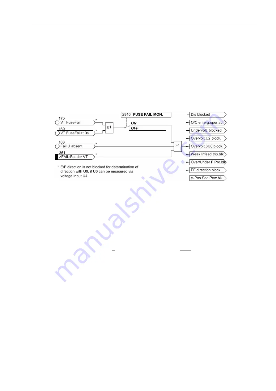
Figure 2-210 shows the effect on the protection functions in case that a measuring voltage is detected by the
„fuse failure monitor“
„VT FuseFail“
(no. 170),
„VT FuseFail>10s“
(no. 169), the additional measuring
voltage failure monitoring
„Fail U absent“
(no. 168) and the binary input of the VT miniature circuit breaker
„>FAIL:Feeder VT“
(no. 361).
Figure 2-210
Effect of the measuring voltage failure
2.24.1.4 Monitoring the Phase Angle of the Positive Sequence Power
This monitoring function allows determining the direction of power flow. You can monitor the phase angle of the
complex power, and generate an indication when the power phasor is inside a settable segment.
One example of this application is the indication of capacitive reactive power. The monitoring indication can
then be used to control the overvoltage protection function. For this purpose, two angles must be set, as shown
in Figure 2-211. In this example,
ϕ
A = 200° and
ϕ
B = 340° has been set.
If the measured phase angle
ϕ
(S
1
) of the positive sequence power is within the area of the P-Q plane delimited
by the angles
ϕ
A and
ϕ
B, the indication
„
ϕ
(PQ Pos. Seq.)“
(No. 130) is output. The angles
ϕ
A and
ϕ
B can
be freely set in the range between 0° and 359°. The area starts at
ϕ
A and extends in a mathematically positive
sense as far as the angle
ϕ
B. A hysteresis of 2° is provided to prevent erroneous indications which might
emerge at the threshold limits.


