Technical Data
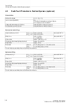
4.9 Earth Fault Protection in Earthed Systems (optional)
SIPROTEC, 7SD5, Manual
C53000-G1176-C169-5, Release date 02.2011
601
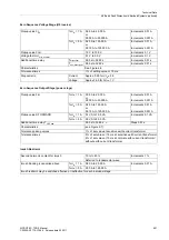
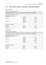
Zero Sequence Voltage Stage (U0 inverse)
Zero Sequence Output Stage (power stage)
Inrush Restraint
Pickup value 3
I
0P
for
I
N
= 1 A
0.05 A to 25.00 A
or
0.003 A to 25.000 A
Increments 0.01 A
Increments 0.001 A
for
I
N
= 5 A
0.25 A to 125.00 A
or
0.015 A to 125.000 A
Increments 0.01 A
Increments 0.001 A
Pickup value 3U
0
>
1.0 V to 10.0 V
Increments 0.1 V
Voltage factor U
0 inv. minimal
0.1 V to 5.0 V
Increments 0.1 V
Additional time delay
T
directional
0.00 s to 32.00 s
Increments 0.01 s
T
non-directional
0.00 s to 32.00 s
Increments 0.01 s
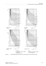
Characteristics
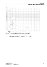
See Figure 4-6
Tolerances times
1 % of setting value or 10 ms
Dropout ratio
Current
Approx. 0.95 for
I
/
I
N
≥
0.5
Voltage
Approx 0.95 for 3U
0
≥
1 V
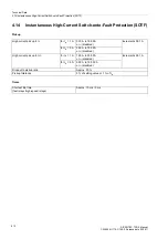
Pickup value 3
I
0P
for
I
N
= 1 A
0.05 A to 25.00 A
or
0.003 A to 25,000 A
Increments 0.01 A
Increments 0.001 A
for
I
N
= 5 A
0.25 A to 125.00 A
or
0.015 A to 125,000 A
Increments 0.01 A
Increments 0.001 A
Pickup value S FORWARD
for
I
N
= 1 A
0.1 VA to 10.0 VA
Increments 0.1 VA
for
I
N
= 5 A
0.5 VA to 50.0 VA
Additional time delay T
3
I
0P add
0.00 s to 30.00 s;
∞
Steps 0.01 s
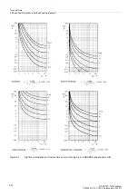
Characteristics
(see Figure 4-7)
Tolerances pickup values
1 % of set value at sensitive earth current transformer
Tolerances times
5 % of set value or 15 ms at sensitive earth current transformer
6 % of set value or 15 ms at normal earth current transformer /
without earth current transformer
Second harmonic content for inrush
10 % to 45 %
Increments 1 %
Referred to fundamental wave
Inrush blocking is cancelled above
for
I
N
= 1 A
0.50 A to 25.00 A
Increments 0.01 A
for
I
N
= 5 A
2.50 A to 125.00 A
Inrush restraint may be switched effective or ineffective for each individual stage.


