Functions
2.1 General
SIPROTEC, 7SD5, Manual
C53000-G1176-C169-5, Release date 02.2011
63
The coupling factors may be determined using the following equations:
where
R
0M
= Mutual zero sequence resistance (coupling resistance) of the line
X
0M
= Mutual zero sequence reactance (coupling reactance) of the line
R
1
= Positive sequence resistance of the line
X
1
= Positive sequence reactance of the line
These values can be applied either to the entire double circuit line length or based on a per unit of line length,
since the quotient is independent of length. Furthermore, it makes no difference whether the quotients are cal-
culated with primary, or secondary values.
These setting values only apply to the protected line and are entered in the addresses
1126
RM/RL
ParalLine
and
1127
XM/XL ParalLine
.
For earth faults on the protected feeder there is in theory no additional distance protection or fault locator mea-
suring error when the parallel line compensation is used. The setting in address
1128
RATIO Par. Comp
is
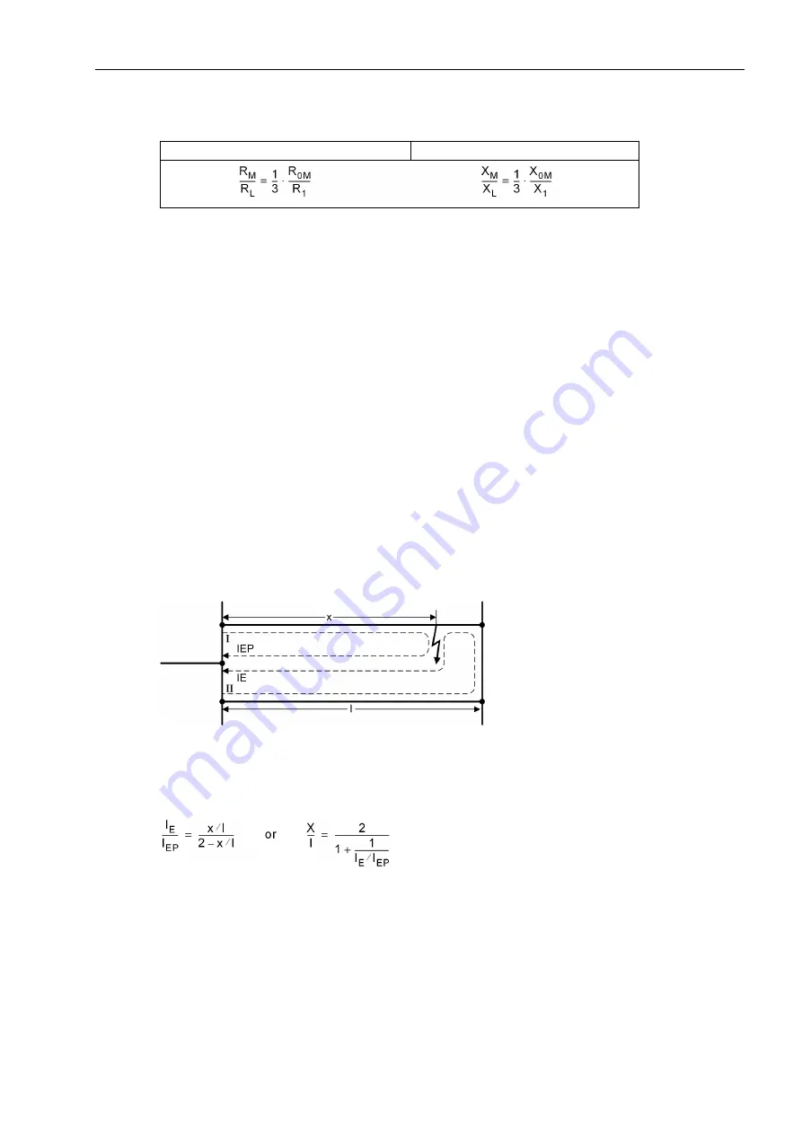
therefore only relevant for earth faults outside the protected feeder. It provides the current ratio
I
E
/
I
EP
for the
earth current balance of the distance protection (in Figure 2-4 for the device at location II), above which com-
pensation should take place. In general, a presetting of 85 % is sufficient. A more sensitive (larger) setting has
no advantage. Only in the case of a severe system asymmetry, or a very small coupling factor (X
M
/X
L
below
approximately 0.4), may a smaller setting be useful. A more detailed explanation of parallel line compensation
can be found in Section 2.5.1 under distance protection.
Figure 2-4
Distance with parallel line compensation at II
The current ratio may also be calculated from the desired distance of the parallel line compensation and vice
versa. The following applies (refer to Figure 2-4):
Resistance ratio:
Reactance ratio:


