Functions
2.11 Measures for Weak and Zero Infeed
SIPROTEC, 7SD5, Manual
C53000-G1176-C169-5, Release date 02.2011
281
2.11.3.2 Setting Notes
Phase selection
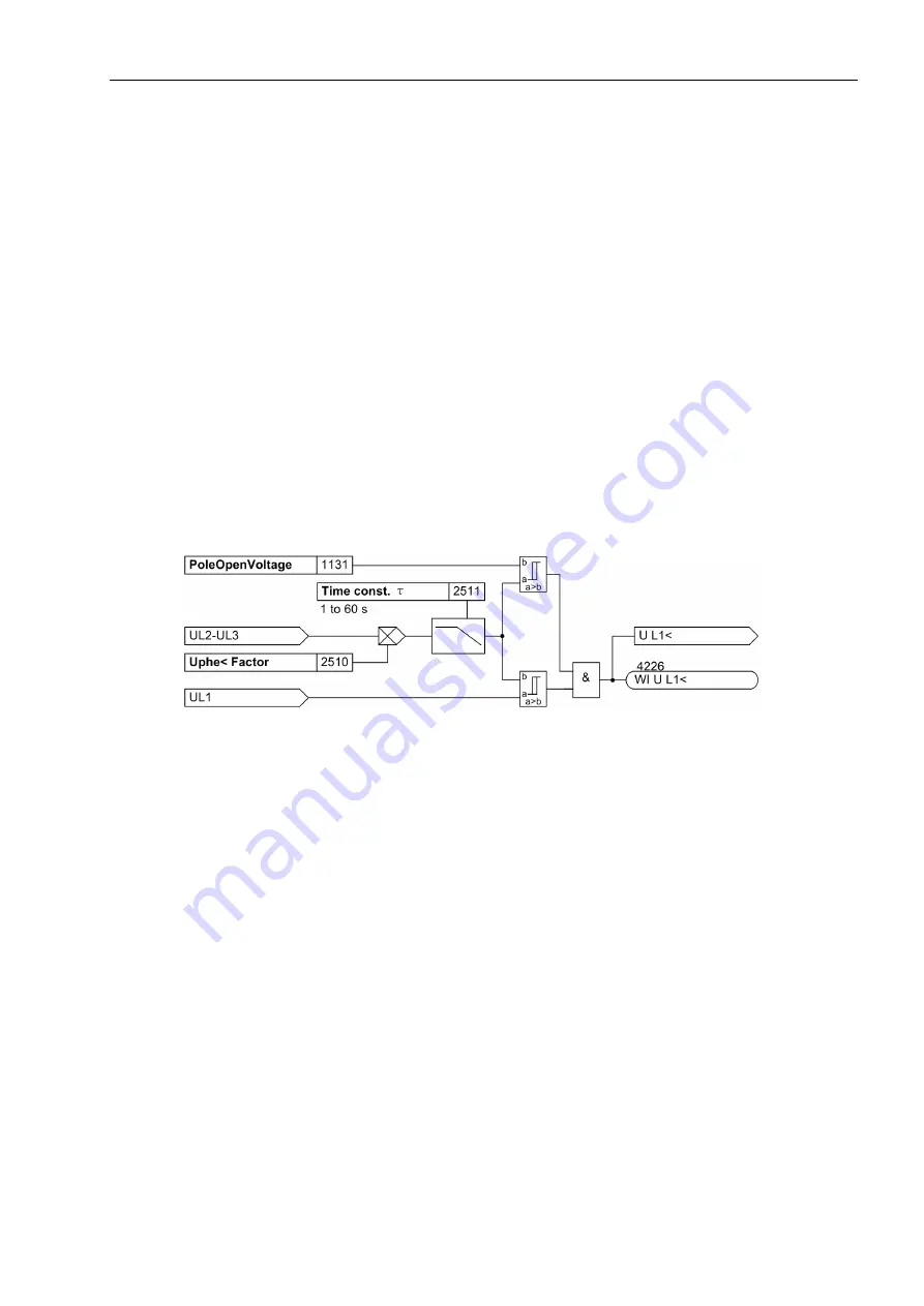
Phase selection is accomplished via undervoltage detection. For this purpose no absolute voltage threshold
in volts is parameterized, but a factor (address
2510
Uphe< Factor
) which is multiplied with the measured
phase-phase voltage, and yields the voltage threshold. This method considers operational deviations from the
rated voltage in the undervoltage threshold and adjusts them to the current conditions.
The undervoltage threshold is created from the mean value of the measured phase-to-phase voltages of the
last 500 ms and delayed via a voltage memory. Thus changes of the phase-to-phase voltage affect the thresh-
old only slowly. The time constant can be set at address
2511
Time const.
τ
. In case of pickup the last
determined voltage threshold of the phase that has picked up remains until a trip command is issued. This
ensures that an influence of the voltage threshold by the fault is avoided for long waiting times. The undervolt-
age is determined for all 3 phases.
If the measured phase-to-phase voltage falls below the threshold (address
1131
PoleOpenVoltage
), under-
voltage is no longer detected in this phase.
Since a positive feedback occurs during tripping, i. e. the measured fault status cannot be eliminated by switch-
ing off, the picked up element drops out after the WI tripping. When the current voltage exceeds the dropout
threshold, a new pickup is possible after a maximum of 1 s.
Figure 2-144
Undervoltage detection for U
L1–E
Instantaneous tripping
An undelayed TRIP command is issued if a receive signal
„>WI reception“
is present and if an undervolt-
age is detected simultaneously. The receive signal is prolonged at address
2512
Rec. Ext.
so that a trip
command is still possible in the event of a quick dropout of the transmitting line end.
To prevent a faulty pickup of the weak infeed function following tripping of the line and reset of the fault detection
by the distance protection function, a pickup is blocked in the corresponding phase. This blocking is maintained
until the receive signal disappears.
If a receive signal applies and no undervoltage is detected, but the zero sequence current threshold
3I0>
Threshold
is exceeded (address
2514
), a fault on the line can be assumed. If this state (receive signal, no
undervoltage and zero sequence current) applies for longer than 500 ms, 3-pole tripping is initiated. The time
delay for the signal „3I0> exceeded“ is set at address
2513
T 3I0> Ext.
. If the zero sequence current
exceeds the threshold
3I0> Threshold
for longer than the set time
T 3I0> alarm
(address
2520
), the
annunciation
„3I0 detected“
is issued.
The non-delayed stage operates only if binary input
„>WI rec. OK“
reports the proper functioning of the
transmission channel.
Moreover, the phase-selective block signals
BLOCK Weak Inf
affect the non-delayed logic. Faulty pickups are
thus prevented, especially after the dedicated line end was shut down.
In address
2530
WI non delayed
the stage for instantaneous tripping is switched
OFF
or
ON
permanently.


