Mounting and Commissioning
3.3 Commissioning
SIPROTEC, 7SD5, Manual
C53000-G1176-C169-5, Release date 02.2011
558
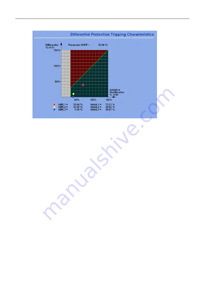
Figure 3-36
Differential and restraint currents - Example of plausible measurements
3.3.9
Checking the Instrument Transformer Connections for More than Two Ends
If there are more than two ends, all tests according to the above Section „Checking the Instrument Transformer
Connections for More than Two Ends“ - as far as they are applicable in this case - have to be repeated for the
other current paths in such a way that all ends of the protected object have been included in the current flow
test at least once. It is not necessary to test every possible current path.
At the ends not involved in the test the circuit breakers remain open. Also pay attention to all safety notes –
especially the DANGER warning in the above Section „Checking the Instrument Transformer Connections with
Two Ends“.
The circuit breakers are reopened after the last test.
If parameters were changed for these tests, they must be returned to their original state after completion of the
test.
3.3.10
Measuring the Operating Time of the Circuit Breaker
Only for Synchronism Check
If the device is equipped with the function for synchronism and voltage check and it is applied, it is necessary
- under asynchronous system conditions - that the operating time of the circuit breaker is measured and set
correctly when closing. If the synchronism check function is not used or only for closing under synchronous
system conditions, this section is irrelevant.
For measuring the operating time a setup as shown in Figure 3-37 is recommended. The timer is set to a range
of 1 s and a graduation of 1 ms.
The circuit breaker is closed manually. At the same time the timer is started. After closing the circuit breaker
poles the voltage U
sy1
or U
sy2
appears and the timer is stopped. The time displayed by the timer is the real circuit
breaker closing time.
If the timer is not stopped due to an unfavourable closing moment, the attempt will be repeated.


