background image

Standard mapping 3-1

2-10

SIPROTEC Modbus - Bus mapping 7UM62

C53000-L1840-C009-03

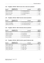
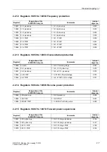
2.2.25 Register 10100: Startup counter for motors

2.2.26 Registers 10101 to 10102: Rotor ground fault protection (R,fn)

2.2.27 Registers 10103 to 10104: DC voltage/current protection

2.2.28 Registers 10105 to 10108: State of the out-of-step protection

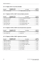
2.2.29 Registers 10109 to 10115: Differential protection

Register

Designation of the

SIPROTEC objects

Comments

Internal 

object no.

10100

66 TRIP

1 =  66 Restart inhibit motor TRIP

4827

Register

Designation of the

SIPROTEC objects

Comments

Internal 

object no.

10101

64R-1 picked up

1 =  64R-1 picked up (Alarm)

5397

10102

64R-2 TRIP

1 =  64R-2 TRIP

5399

Register

Designation of the

SIPROTEC objects

Comments

Internal 

object no.

10103

DC Prot.pick.up

1 =  DC protection picked up

5306

10104

DC Prot. TRIP

1 =  DC protection TRIP

5307

Register

Designation of the

SIPROTEC objects

Comments

Internal 

object no.

10105

78 det. char. 1

1 =  78 characteristic 1 picked up

5069

10106

78 det. char. 2

1 =  78 characteristic 2 picked up

5070

10107

78 TRIP char. 1

1 =  78 TRIP characteristic 1

5071

10108

78 TRIP char. 2

1 =  78 TRIP characteristic 2

5072

Register

Designation of the

SIPROTEC objects

Comments

Internal 

object no.

10109

87 picked up

1 =  87 Differential protection picked up

5631

10110

87 TRIP

1 =  87 Differential protection TRIP

5671

10111

87 TRIP Phase A

1 =  87 Differential protection: TRIP Phase A

5672

10112

87 TRIP Phase B

1 =  87 Differential protection: TRIP Phase B

5673

10113

87 TRIP Phase C

1 =  87 Differential protection: TRIP Phase C

5674

10114

87 Diff> TRIP

1 =  87 Differential prot.: TRIP by IDIFF>

5691

10115

87 Diff>> TRIP

1 =  87 Diff>> TRIP

5692

Summary of Contents for SIPROTEC4 7UM62

Page 1: ...l 2004 C53000 L1840 C009 03 SIPROTEC Multifunctional machine protection 7UM62 Communication module Modbus Bus mapping Preface Table of contents Data in the Modbus registers 1 Standard mapping 3 1 2 Standard mapping 3 2 3 Index ...

Page 2: ...chnical improvements without notice Copyright Copyright Siemens AG 2004 All rights reserved Dissemination or reproduction of this document or evaluation and commu nication of its contents is not authorized except where expressly permitted Violations are liable for damages All rights reserved particularly for the purposes of patent application or trademark registration Registered trademarks SIPROTE...

Page 3: ...ning of the SIPROTEC devices you find in the SIPROTEC4 System Manual order no E50417 H1176 C151 Modbus communication profile documentation The following additional manual informs you about the data types bus specific param eters and hardware inteface of the Modbus slave modul of the SIPROTEC devices Modbus specification The Modbus specification with a detailed explanation of the Modbus protocol is...

Page 4: ...ation module Modbus Communication profile ref to page i Modbus standard mappings 3 1 to 3 n n device type dependent number of standard mappings Additional Support For questions regarding SIPROTEC4 devices please contact your Siemens repre sentative Training courses Individual course offerings may be found in our Training Catalog and questions can be directed to our Training Centre Please contact y...

Page 5: ...lso applies to selection items for selection menus Annunciations or identifiers for information produced by the device or required by other devices or from the switchgear is shown in mono script same point size and placed into quotation marks For diagrams in which the identifier type results from the representation itself text con ventions may differ from the above mentioned Warning During operati...

Page 6: ...Preface iv SIPROTEC Modbus Bus mapping C53000 L1840 C009 03 ...

Page 7: ...0324 Statistic values new with 7UM62 V4 10 Registers 40351 to 40410 Min Max values new with 7UM62 V4 10 March 26th 2002 2 1 New Standard mapping 3 2 with Event recorder Reorganisation of the manual Chap 1 Descriptions to the Modbus register map organization and notes for evaluation of selected SIPROTEC Objects Chap 2 Standard mapping 3 1 Chap 3 Standard mapping 3 2 March 17th 2003 Chap 1 1 3 2 33 ...

Page 8: ...Revision index vi SIPROTEC Modbus Bus mapping C53000 L1840 C009 03 ...

Page 9: ...ings 2 2 2 1 3 Registers 00027 to 00030 Double commands 2 3 2 1 4 Registers 00257 to 00264 Exception Flags 2 3 2 2 Input Status registers 1X references 2 4 2 2 1 Registers 10001 to 10008 User defined annunciations 2 4 2 2 2 Registers 10009 to 10013 Overcurrent time protection I 2 4 2 2 3 Registers 10014 to 10019 Overcurrent time protection I 2 4 2 2 4 Registers 10020 to 10023 Inverse time overcurr...

Page 10: ...ion 2 10 2 2 30 Registers 10116 to 10117 Stator ground fault protection 100 2 11 2 2 31 Registers 10118 to 10119 Rotor ground fault protection 1 3 Hz 2 11 2 2 32 Registers 10120 to 10121 Restricted ground fault protection 2 11 2 2 33 Registers 10122 to 10129 Fault indications of protection functions 2 11 2 3 Input registers 3X references 2 12 2 4 Holding registers 4X references 2 13 2 4 1 Register...

Page 11: ...er 10094 Trip coil monitor 3 9 3 2 23 Registers 10095 to 10096 Inverse undervoltage protection 3 9 3 2 24 Registers 10097 to 10099 Startup supervision of motors 3 9 3 2 25 Register 10100 Startup counter for motors 3 10 3 2 26 Registers 10101 to 10102 Rotor ground fault protection R fn 3 10 3 2 27 Registers 10103 to 10104 DC voltage current protection 3 10 3 2 28 Registers 10105 to 10108 State of t...

Page 12: ...Table of contents x SIPROTEC Modbus Bus mapping C53000 L1840 C009 03 ...
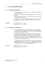
Page 13: ...ters 1 This chapter gives explanations to the descriptions of the Modbus register map organ isation Standard mappings in the following chapters 2 and 3 and notes for evaluation of selected SIPROTEC objects 1 1 Explanations 1 2 1 2 Modbus registers 1 5 1 3 Notes to SIPROTEC objects 1 7 ...

Page 14: ...he Standard mapping 3 1 contains Coil Status registers 2 Double commands incl 2 Double point indications as checkback indication 18 Single commands incl 18 Single point indications as checkback indication 8 Single point indications Exception Flags Input Status registers 129 Single point indications Input registers 15 Measured values Holding registers System information Time synchronization 16 Sing...

Page 15: ...registers 21 Measured values2 Holding registers System information Time synchronization 16 Single point indications Diagnostic Register 4 Metered measurands Counters 1 Measured value in output direction Cooling medium temperature 12 Statistic values 12Min Max values of measured values Event recorder Sequence of Events 1 129 Single point indications in version V02 01 01 of the Standard mapping 3 2 ...

Page 16: ...n the register mapping Register Designation of the SIPROTEC objects Comments Scaling 32767corresponds to Internal object no 30001 IA S2 Operat meas current A side 2 327 67 724 Register Designation of the SIPROTEC objects Comments Internal object no 10009 50 51 1 Ph A PU 1 50 51 1 Phase A picked up 1811 Note The description of the standard mappings contains the pre allocation of the map ping files ...

Page 17: ...put channels as well as the annunciations generated in the SIPROTEC device e g protection annunciations status annunciations References Standard mapping 3 1 ref to chap 2 2 Standard mapping 3 2 ref to chap 3 2 Note The allocation of the output relays to the switching devices and to the output chan nels is defined during parameterization of the SIPROTEC devices Depending on the device composition t...

Page 18: ...Sequence of Events then Holding registers are used for reading the Event recorder entries References Standard mapping 3 1 ref to chap 2 4 Standard mapping 3 2 ref to chap 3 4 Note Depending on the device composition not all of the indicated analog inputs and corresponding Modbus registers may be available in the SIPROTEC device The transferred percentage values are with reference to the nominal va...

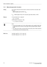
Page 19: ...rred in per cent to the 7UM62 The protection device must be informed about the 100 corresponding tempera ture using parameter 49 Temperature for Scaling function 49 Thermal Overload parameter address 1608 The temperature value via Modbus is only taken into account and shown at the SIPROTEC device if the parameter 49 Temperature Input function 49 Thermal Overload parameter address 1607 has the valu...

Page 20: ...ddress 0252 Example In the parameter set is configured Snom 5 27 MVA 60000 impulses correspond so that 1 h 5 27 MVA 5 27 MVAh References Standard mapping 3 1 ref to chap 2 4 4 Standard mapping 3 2 ref to chap 3 4 4 Note The type of the update cyclic with or without deletion and the update interval must be programmed for the metered measurands with the parameterization software DIGSI The scaling of...

Page 21: ...ter describes the register map organisation of the Modbus slave of the SIPROTEC device 7UM62 at use of Standard mapping 3 1 2 1 Coil Status registers 0X references 2 2 2 2 Input Status registers 1X references 2 4 2 3 Input registers 3X references 2 12 2 4 Holding registers 4X references 2 13 ...

Page 22: ...roup B 0 not permitted 1 Activation of setting group B 54 Indication Setting Group B 0 Setting group B is not active 1 Setting group B is active 00003 00010 reseved The value 0 is always returned if reading A write access is rejected in the SIPROTEC device Register Designation of the SIPROTEC objects Comments Internal object no 00011 user defined not pre allocated 00012 user defined not pre alloca...

Page 23: ...f these registers are also readable using function Read Exception Status function code 7 Installation specific SIPROTEC objects can be routed on these register positions using parameterization system DIGSI Register Designation of the SIPROTEC objects Comments Internal object no 00027 user defined ON not pre allocated 00028 user defined OFF 00029 user defined ON not pre allocated 00030 user defined...

Page 24: ...user defined not pre allocated 10005 user defined not pre allocated 10006 user defined not pre allocated 10007 user defined not pre allocated 10008 user defined not pre allocated Register Designation of the SIPROTEC objects Comments Internal object no 10009 50 51 1 Ph A PU 1 50 51 1 Phase A picked up 1811 10010 50 51 1 Ph B PU 1 50 51 1 Phase B picked up 1812 10011 50 51 1 Ph C PU 1 50 51 1 Phase ...

Page 25: ...PROTEC objects Comments Internal object no 10024 49 O L I Alarm 1 49 Overload Current Alarm I alarm 1515 10025 49 O L ΘAlarm 1 49 Thermal Overload Alarm 1516 10026 49 Th O L TRIP 1 49 Thermal Overload TRIP 1521 Register Designation of the SIPROTEC objects Comments Internal object no 10027 46 1 Warn 1 46 1 Current warning stage 5156 10028 46 1 picked up 1 46 1 picked up 5165 10029 46 2 picked up 1 ...

Page 26: ...67GN TRIP 5193 Register Designation of the SIPROTEC objects Comments Internal object no 10041 27TN 59TN PU 1 27TN 59TN with 3rd harmomic picked up 5567 10042 27TN 59TN TRP 1 27TN 59TN with 3rd harmomic TRIP 5568 Register Designation of the SIPROTEC objects Comments Internal object no 10043 59 1 picked up 1 59 1 Overvoltage V picked up 6568 10044 59 2 picked up 1 59 2 Overvoltage V picked up 6571 1...

Page 27: ... 10057 81 3 TRIP 1 81 3 TRIP 5238 10058 81 4 TRIP 1 81 4 TRIP 5239 Register Designation of the SIPROTEC objects Comments Internal object no 10059 24 warn 1 24 V f warning stage 5367 10060 24 1 picked up 1 24 1 V f picked up 5370 10061 24 2 picked up 1 24 2 V f picked up 5373 10062 24 th TRIP 1 24 TRIP of thermal stage 5372 10063 24 2 TRIP 1 24 2 TRIP of V f stage 5371 Register Designation of the S...

Page 28: ...p 1 40 picked up 5337 10074 40 1 TRIP 1 40 characteristic 1 TRIP 5344 10075 40 2 TRIP 1 40 characteristic 2 TRIP 5345 10076 40 V TRIP 1 40 characteristic Vexc TRIP 5346 10077 40 3 TRIP 1 40 characteristic 3 TRIP 5343 Register Designation of the SIPROTEC objects Comments Internal object no 10078 50BF pickup 1 50BF picked up 1455 10079 50BF TRIP 1 50BF TRIP 1471 Register Designation of the SIPROTEC ...

Page 29: ...ral TRIP 4577 10091 Ext 4 Gen TRP 1 External trip 4 General TRIP 4597 Register Designation of the SIPROTEC objects Comments Internal object no 10092 50 27 picked up 1 50 27 picked up 5547 10093 50 27 TRIP 1 50 27 TRIP 5548 Register Designation of the SIPROTEC objects Comments Internal object no 10094 FAIL Trip cir 1 74TC Failure Trip Circuit 6865 Register Designation of the SIPROTEC objects Commen...

Page 30: ...omments Internal object no 10103 DC Prot pick up 1 DC protection picked up 5306 10104 DC Prot TRIP 1 DC protection TRIP 5307 Register Designation of the SIPROTEC objects Comments Internal object no 10105 78 det char 1 1 78 characteristic 1 picked up 5069 10106 78 det char 2 1 78 characteristic 2 picked up 5070 10107 78 TRIP char 1 1 78 TRIP characteristic 1 5071 10108 78 TRIP char 2 1 78 TRIP char...

Page 31: ...able with 7UM62 V4 10 or higher Register Designation of the SIPROTEC objects Comments Internal object no 10116 SGF100 Alarm 1 Stator ground fault prot 100 Alarm stage 5487 10117 SGF100 TRIP 1 Stator ground fault prot 100 TRIP 5489 Register Designation of the SIPROTEC objects Comments Internal object no 10118 64R 1_3Hzpickup 1 64R 1 1 3Hz picked up Alarm 5403 10119 64R 2_3Hz TRIP 1 64R 2 1 3Hz TRIP...

Page 32: ...meas current B side 2 327 67 725 30003 IC S2 Operat meas current C side 2 327 67 726 30004 Va b Va b 327 67 624 30005 Vb c Vb c 327 67 625 30006 Vc a Vc a 327 67 626 30007 P P active power 327 67 641 30008 Q Q reactive power 327 67 642 30009 f Frequency 327 67 Hz 644 30010 I2 I2 negative sequence 327 67 606 30011 Θ Θ trip Temperature rise for warning and trip 327 67 801 30012 user defined not pre ...

Page 33: ...evision Example Register 40009 0001H register 40010 0205H Revision 1 2 5 40011 40026 MLFB order number of the SIPROTEC device string max 32 characters Example 7UM62115EA923CA0 0D 40027 40034 Date and time of mapping data generation string max 16 characters Example 140201095747330 corresponds to Date Feb 14th 2001 Time 09 hours 57 min 47 sec and 330 milliseconds 40035 40036 Number of selected stand...

Page 34: ...r restart 51 40129 21 user defined not pre allocated 40129 22 ProtActive 1 At least one protection function is active 52 40129 23 Error Sum Alarm 1 Error with a summary alarm ON 140 40129 24 Alarm Sum Event 1 Alarm summary event ON 160 40129 25 Relay PICKUP 1 Relay PICKUP group signal 501 40129 26 Relay TRIP 1 Relay GENERAL TRIP command 511 40129 27 Operat Cond 1 Suitable measured quantities are p...

Page 35: ...ILLEGAL_DATA_VALUE Register Designation of the SIPROTEC objects Comments Scaling 231 1 corresponds to Internal object no 40201 40202 Wp Wp Forward Metered measurand derived from measured values 231 1 impulses 924 40203 40204 Wq Wq Forward Metered measurand derived from measured values 231 1 impulses 925 40205 40206 Wp Wp Reverse Metered measurand derived from measured values 231 1 impulses 928 402...

Page 36: ...ode 03 ILLEGAL_DATA_VALUE Register Designation of the SIPROTEC objects Comments Internal object no 40301 40302 user defined not pre allocated 40303 40304 user defined not pre allocated 40305 40306 user defined not pre allocated 40307 40308 user defined not pre allocated 40309 40310 user defined not pre allocated 40311 40312 user defined not pre allocated 40313 40314 user defined not pre allocated ...

Page 37: ...ents Scaling 32767 corre sponds to Internal object no 40351 user defined Min Max not pre allocated 40352 _ 40355 Time Date Time and Date of user defined Min Max 40356 user defined Min Max not pre allocated 40357 _ 40360 Time Date Time and Date of user defined Min Max 40361 user defined Min Max not pre allocated 40362 _ 40365 Time Date Time and Date of user defined Min Max 40366 user defined Min Ma...

Page 38: ...d Min Max not pre allocated 40397 _ 40400 Time Date Time and Date of user defined Min Max 40401 user defined Min Max not pre allocated 40402 _ 40405 Time Date Time and Date of user defined Min Max 40406 user defined Min Max not pre allocated 40407 _ 40410 Time Date Time and Date of user defined Min Max Register Designation of the SIPROTEC objects Comments Scaling 32767 corre sponds to Internal obj...

Page 39: ...ter describes the register map organisation of the Modbus slave of the SIPROTEC device 7UM62 at use of Standard mapping 3 2 3 1 Coil Status registers 0X references 3 2 3 2 Input Status registers 1X references 3 4 3 3 Input registers 3X references 3 12 3 4 Holding registers 4X references 3 13 ...

Page 40: ...roup B 0 not permitted 1 Activation of setting group B 54 Indication Setting Group B 0 Setting group B is not active 1 Setting group B is active 00003 00010 reseved The value 0 is always returned if reading A write access is rejected in the SIPROTEC device Register Designation of the SIPROTEC objects Comments Internal object no 00011 user defined not pre allocated 00012 user defined not pre alloca...

Page 41: ...f these registers are also readable using function Read Exception Status function code 7 Installation specific SIPROTEC objects can be routed on these register positions using parameterization system DIGSI Register Designation of the SIPROTEC objects Comments Internal object no 00027 user defined ON not pre allocated 00028 user defined OFF 00029 user defined ON not pre allocated 00030 user defined...

Page 42: ...user defined not pre allocated 10005 user defined not pre allocated 10006 user defined not pre allocated 10007 user defined not pre allocated 10008 user defined not pre allocated Register Designation of the SIPROTEC objects Comments Internal object no 10009 50 51 1 Ph A PU 1 50 51 1 Phase A picked up 1811 10010 50 51 1 Ph B PU 1 50 51 1 Phase B picked up 1812 10011 50 51 1 Ph C PU 1 50 51 1 Phase ...

Page 43: ...PROTEC objects Comments Internal object no 10024 49 O L I Alarm 1 49 Overload Current Alarm I alarm 1515 10025 49 O L ΘAlarm 1 49 Thermal Overload Alarm 1516 10026 49 Th O L TRIP 1 49 Thermal Overload TRIP 1521 Register Designation of the SIPROTEC objects Comments Internal object no 10027 46 1 Warn 1 46 1 Current warning stage 5156 10028 46 1 picked up 1 46 1 picked up 5165 10029 46 2 picked up 1 ...

Page 44: ...67GN TRIP 5193 Register Designation of the SIPROTEC objects Comments Internal object no 10041 27TN 59TN PU 1 27TN 59TN with 3rd harmomic picked up 5567 10042 27TN 59TN TRP 1 27TN 59TN with 3rd harmomic TRIP 5568 Register Designation of the SIPROTEC objects Comments Internal object no 10043 59 1 picked up 1 59 1 Overvoltage V picked up 6568 10044 59 2 picked up 1 59 2 Overvoltage V picked up 6571 1...

Page 45: ... 10057 81 3 TRIP 1 81 3 TRIP 5238 10058 81 4 TRIP 1 81 4 TRIP 5239 Register Designation of the SIPROTEC objects Comments Internal object no 10059 24 warn 1 24 V f warning stage 5367 10060 24 1 picked up 1 24 1 V f picked up 5370 10061 24 2 picked up 1 24 2 V f picked up 5373 10062 24 th TRIP 1 24 TRIP of thermal stage 5372 10063 24 2 TRIP 1 24 2 TRIP of V f stage 5371 Register Designation of the S...

Page 46: ...p 1 40 picked up 5337 10074 40 1 TRIP 1 40 characteristic 1 TRIP 5344 10075 40 2 TRIP 1 40 characteristic 2 TRIP 5345 10076 40 V TRIP 1 40 characteristic Vexc TRIP 5346 10077 40 3 TRIP 1 40 characteristic 3 TRIP 5343 Register Designation of the SIPROTEC objects Comments Internal object no 10078 50BF pickup 1 50BF picked up 1455 10079 50BF TRIP 1 50BF TRIP 1471 Register Designation of the SIPROTEC ...

Page 47: ...ral TRIP 4577 10091 Ext 4 Gen TRP 1 External trip 4 General TRIP 4597 Register Designation of the SIPROTEC objects Comments Internal object no 10092 50 27 picked up 1 50 27 picked up 5547 10093 50 27 TRIP 1 50 27 TRIP 5548 Register Designation of the SIPROTEC objects Comments Internal object no 10094 FAIL Trip cir 1 74TC Failure Trip Circuit 6865 Register Designation of the SIPROTEC objects Commen...

Page 48: ...omments Internal object no 10103 DC Prot pick up 1 DC protection picked up 5306 10104 DC Prot TRIP 1 DC protection TRIP 5307 Register Designation of the SIPROTEC objects Comments Internal object no 10105 78 det char 1 1 78 characteristic 1 picked up 5069 10106 78 det char 2 1 78 characteristic 2 picked up 5070 10107 78 TRIP char 1 1 78 TRIP characteristic 1 5071 10108 78 TRIP char 2 1 78 TRIP char...

Page 49: ...gister Designation of the SIPROTEC objects Comments Internal object no 10116 SGF100 Alarm 1 Stator ground fault prot 100 Alarm stage 5487 10117 SGF100 TRIP 1 Stator ground fault prot 100 TRIP 5489 Register Designation of the SIPROTEC objects Comments Internal object no 10118 64R 1_3Hzpickup 1 64R 1 1 3Hz picked up Alarm 5403 10119 64R 2_3Hz TRIP 1 64R 2 1 3Hz TRIP 5407 Register Designation of the ...

Page 50: ...c a Vc a 327 67 626 30007 P P active power 327 67 641 30008 Q Q reactive power 327 67 642 30009 f Frequency 327 67 Hz 644 30010 I2 I2 negative sequence 327 67 606 30011 Θ Θ trip Temperature rise for warning and trip 327 67 801 30012 user defined not pre allocated 30013 IA S1 Operat meas current A side 1 327 67 721 30014 IB S1 Operat meas current B side 1 327 67 722 30015 IC S1 Operat meas current ...

Page 51: ...evision Example Register 40009 0001H register 40010 0205H Revision 1 2 5 40011 40026 MLFB order number of the SIPROTEC device string max 32 characters Example 7UM62115EA923CA0 0D 40027 40034 Date and time of mapping data generation string max 16 characters Example 140201095747330 corresponds to Date Feb 14th 2001 Time 09 hours 57 min 47 sec and 330 milliseconds 40035 40036 Number of selected stand...

Page 52: ...r restart 51 40129 21 user defined not pre allocated 40129 22 ProtActive 1 At least one protection function is active 52 40129 23 Error Sum Alarm 1 Error with a summary alarm ON 140 40129 24 Alarm Sum Event 1 Alarm summary event ON 160 40129 25 Relay PICKUP 1 Relay PICKUP group signal 501 40129 26 Relay TRIP 1 Relay GENERAL TRIP command 511 40129 27 Operat Cond 1 Suitable measured quantities are p...

Page 53: ...ILLEGAL_DATA_VALUE Register Designation of the SIPROTEC objects Comments Scaling 231 1 corresponds to Internal object no 40201 40202 Wp Wp Forward Metered measurand derived from measured values 231 1 impulses 924 40203 40204 Wq Wq Forward Metered measurand derived from measured values 231 1 impulses 925 40205 40206 Wp Wp Reverse Metered measurand derived from measured values 231 1 impulses 928 402...

Page 54: ...ode 03 ILLEGAL_DATA_VALUE Register Designation of the SIPROTEC objects Comments Internal object no 40301 40302 user defined not pre allocated 40303 40304 user defined not pre allocated 40305 40306 user defined not pre allocated 40307 40308 user defined not pre allocated 40309 40310 user defined not pre allocated 40311 40312 user defined not pre allocated 40313 40314 user defined not pre allocated ...

Page 55: ...ents Scaling 32767 corre sponds to Internal object no 40351 user defined Min Max not pre allocated 40352 _ 40355 Time Date Time and Date of user defined Min Max 40356 user defined Min Max not pre allocated 40357 _ 40360 Time Date Time and Date of user defined Min Max 40361 user defined Min Max not pre allocated 40362 _ 40365 Time Date Time and Date of user defined Min Max 40366 user defined Min Ma...

Page 56: ...d Min Max not pre allocated 40397 _ 40400 Time Date Time and Date of user defined Min Max 40401 user defined Min Max not pre allocated 40402 _ 40405 Time Date Time and Date of user defined Min Max 40406 user defined Min Max not pre allocated 40407 _ 40410 Time Date Time and Date of user defined Min Max Register Designation of the SIPROTEC objects Comments Scaling 32767 corre sponds to Internal obj...

Page 57: ...I ref to chap Customization of the allocations in the manual SIPROTEC Communication module Modbus Communication profile 1 A write access is rejected with exception code 03 ILLEGAL_DATA_VALUE Register Designation Comments 40601 No of Event recorder entries Number of Event recorder entries which still were not read 40602 SOE_Control Handshake register read write access 40603 Message block 1 Register...

Page 58: ...Standard mapping 3 2 3 20 SIPROTEC Modbus Bus mapping 7UM62 C53000 L1840 C009 03 ...

Page 59: ...art CRC Cyclical Redundancy Check DC Double Command DIGSI Parameterization system parameterization software for SIPROTEC devices DP Double point indication Input data Input direction Data from the Modbus slave to the Modbus master LRC Longitudinal Redundancy Check LSB Least Significant Byte Mapping Allocation of the SIPROTEC data objects to the positions in the Modbus register map MSB Most Signifi...

Page 60: ...Glossary 4 2 SIPROTEC Modbus Bus mapping C53000 L1840 C009 03 ...
Page 61: ...e commands 2 3 3 3 Double point indications 2 3 3 3 E Event recorder 3 19 F Fault indications of protection functions 2 11 3 11 Forward power supervision 2 7 3 7 Frequency protection 2 7 3 7 Fuse Failure Monitor 2 8 3 8 I Impedance protection 2 8 3 8 Inadvertent energisation protection 2 9 3 9 Inverse undervoltage protection 2 9 3 9 M Measured values 1 6 1 7 2 12 3 12 Min Max values 2 17 3 17 Mess...

Page 62: ...3 9 State of the out of step protection 2 10 3 10 Statistic values 2 16 3 16 Stator ground fault protection 2 6 3 6 100 2 11 3 11 T Target audience P ii Thermal overload protection 2 5 3 5 Time synchronization 2 13 3 13 Trip coil monitor 2 9 3 9 Typographic conventions P iii U Unbalanced load protection 2 5 3 5 Underexcitation protection 2 8 3 8 Undervoltage protection 2 6 3 6 V Validity of the ma...

Page 63: ...in Germany Dear reader printing errors can never be entirely eliminated therefore should you come across any when reading this manual kindly enter them in this form together with any comments or suggestions for improvement that you may have From Name Company Dept Address Phone no Fax no Corrections Suggestions ...

Page 64: ...r communication of the contents thereof are forbidden with out express authority Offenders are liable to the payment of damages All rights are reserved in the event of the grant of a patent or the registration of a utility model or design Order no C53000 L1840 C009 03 Siemens Aktiengesellschaft ...

Reviews: