background image

SIREMOBIL

 English
Print No.: SPR2-230.812.02.02.02 

Doc. Gen. Date:

02.06

Replaces: SPR2-230.812.02.01.02


© Sieme ns AG  20 04

The reproduction, transmission or
use of this document or its contents
is not permitted without express
written authority. Offenders will be
liable for damages. All rights,
including rights created by patent
grant or registration of a utility
model 

_

or

_

 design,

_

are

_

 reserved.

SP

System Manual

Installation of TFT displays

Installation Instructions

Summary of Contents for SIREMOBIL

Page 1: ...ion transmission or use of this document or its contents is not permitted without express written authority Offenders will be liable for damages All rights including rights created by patent grant or registration of a utility model _or_ design _are_ reserved SP System Manual Installation of TFT displays Installation Instructions ...

Page 2: ...evels Disclaimer The installation and service of equipment described herein is to be performed by qualified personnel who are employed by Siemens or one of its affiliates or who are otherwise authorized by Siemens or one of its affiliates to provide such services Assemblers and other persons who are not employed by or otherwise directly affiliated with or autho rized by Siemens or one of its affil...

Page 3: ... 2 1 Installation of the video and power line cables in the monitor trolley 2 3 Installation of the support arm on the monitor trolley 2 3 BARCO display 2 3 Adjusting the support arm to the size of the TFT display 2 4 Installation 2 5 Protective ground wiring of the support arm 2 6 Wiring the radiation indicators of the support arm 2 6 Wiring of the displays 2 7 BARCO displays 2 7 Running the cabl...

Page 4: ...0 4 Contents SIREMOBIL SPR2 230 812 02 Page 4 of 4 Siemens AG System Manual Rev 02 02 06 CS PS SP Medical Solutions Page ...

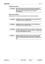
Page 5: ...000 860 01 DANGER indicates an immediate danger that if disregarded will cause death or serious physical injury WARNING indicates a possible danger that if disregarded can cause death or serious physical injury CAUTION used with the safety alert icon indicates a possible dan ger that if disregarded will or can lead to minor or moderate phys ical injury and or damage to property NOTICE used without...

Page 6: ...L systems with available tube moni tors installed on the monitor trolley 37 77 880 Parts required 1 Auxiliary devices required 1 Tool case Required Documents Replacement instructions of the delivered TFT displays See CS Intranet CB Doc of the corresponding system Service System manual for the system Logbook for the system IQ quick test of the system Upgrade Kit for TFT Displays 07141125 The corres...

Page 7: ...1 Remove the shielding plates Fig 2 Remove the connection housing only for SIMOMED N monitor 11 02 628 Fig 3 Unplug all cables from the monitor to be replaced In each case loosen the 2 screws at the monitor mounting Fig 4 Lift down both monitors Reattach all previously removed parts to the monitor Fig 1 Monitor cover Fig 2 Shielding plate Fig 3 Connection housing Fig 4 Monitor attachment Mark for ...

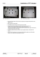
Page 8: ... around the central cable bush Ê Fig 5 4 metal bolts are inserted in these holes and they are thus closed Drive out the 4 metal bolts downwards with a drift or another round object Remove the 4 metal bolts from the monitor trolley Lift off the central blind cover and close one of the cable bushes on the side with it Fig 6 Close off the 2nd cable bush on the side and the 8 fastening holes around th...

Page 9: ...ards through the holder of the support arm 2 Fig 8 through the center cable bush of the monitor trolley and through the lateral rail to the ON OFF assembly Fig 7 and connect them to the terminal blocks Connect the brown cable ends to terminal block X2 1 Connect the blue cable ends to terminal block X2 2 Connect the protective ground Ge Gn to the protective conductor bars 1 Fig 7 Thread the video c...

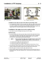
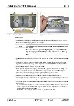
Page 10: ...Calculation of the distances 1 Fig 10 Setting the distances results in a distance of approx 1 cm between the top and bottom edge of the TFT displays on the one hand and the tubes of the support arm on the oth er hand Fig 9 Collision protection Fig 10 Adjustment of the support arm You can adjust the width of the support arm and the distance between the top and bottom tube to adapt the support arm t...

Page 11: ...properly positioned tighten the fixing screws firmly Reattach the collision protection on the left hand and right hand side Fig 9 If it is required to adjust the width insert a spacer ring on both sides then push the colli sion protection in the tube and retighten its screws If required correct the distance between the displays and the top and bottom tube of the support arm It is recommended to le...

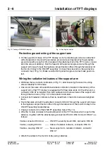
Page 12: ...ble of the additional radiation indicator included in the delivery of the support arm of the TFT display is equipped with 2 free cable ends On the other end a connector D50 X7 is installed Run both cable ends in the lower tube of the support arm through the two bores 1 Fig 13 to the radiation indicators Connect both radiation indicators then re insert them in the bottom tube and retighten them Rou...

Page 13: ...g in the power cables Close both covers again located above the display connections Running the cables 2 If required retract the power line cables and video cables into the monitor trolley Route the cables without sharp bending radius It is recommended to ensure that the cables are covered by both support arm rails in the area between support arm base and the displays see Fig 11 The cables should ...

Page 14: ...SIREMOBIL SPR2 230 812 02 Page 8 of 8 Siemens AG System Manual Rev 02 02 06 CS PS SP Medical Solutions 2 8 Installation of TFT displays This page is intentionally left blank ...

Page 15: ...instructions TD00 000 841 17 Refer to the System dependent settings chapter of the instructions Concluding work 3 Close all covers again Make sure that the protective ground wire connections make good contact Perform the protective ground wire test according to TD00 000 860 01 The protective ground wire resistance must not exceed 0 2 ohms Perform the IQ quick test of the system Perform the country...

Page 16: ...SIREMOBIL SPR2 230 812 02 Page 2 of 2 Siemens AG System Manual Rev 02 02 06 CS PS SP Medical Solutions 3 2 Settings This page is intentionally left blank ...

Page 17: ...Siemens AG SPR2 230 812 02 Page 1 of 2 SIREMOBIL Medical Solutions Rev 02 02 06 CS PS SP System Manual Changes to previous version 4 Editorial revised Descriptions for SIEMENS and other TFT displays deleted ...

Page 18: ...SIREMOBIL SPR2 230 812 02 Page 2 of 2 Siemens AG System Manual Rev 02 02 06 CS PS SP Medical Solutions 4 2 Changes to previous version This page intentionally left blank ...

Reviews: