background image


SIRIUS 3RM1 motor starter 
Manual, 06/2016, A5E0345285095020A/RS-AE/005 

87


Mounting 

5.1


Warning notices 

Warning notices before installation, wiring, and commissioning 


DANGER 

Hazardous voltage.  

Will cause death or serious injury. 
Turn off and lock out all power supplying this device before working on this device. 


NOTICE 
Damage caused by electrostatic charge 
When handling and installing the 3RM1 motor starters, ensure that the components are 

protected from electrostatic charge. Changes to the system configuration and wiring are 

only permissible in the voltage-free state. 

Connection of 3RM11 / 3RM13 Failsafe motor starters is only permissible when the power 

supply units (PELV and SELV) are switched off. 


Summary of Contents for SIRIUS 3RM1

Page 1: ...Manual Industrial Controls Load Feeders and Motor Starters SIRIUS 3RM1 Motor Starter Edition 06 2016 siemens com ...

Page 2: ......

Page 3: ...______________ ___________________ ___________________ Industrial Controls Load feeders and motor starters SIRIUS 3RM1 motor starter Manual 06 2016 A5E0345285095020A RS AE 005 Introduction 1 Product specific safety information 2 Description 3 Configuration 4 Mounting 5 Connection 6 Operator control and monitoring 7 Service and maintenance 8 Technical data 9 Dimension drawings 10 Circuit diagrams 1...

Page 4: ...only by personnel qualified for the specific task in accordance with the relevant documentation in particular its warning notices and safety instructions Qualified personnel are those who based on their training and experience are capable of identifying risks and avoiding potential hazards when working with these products systems Proper use of Siemens products Note the following WARNING Siemens pr...

Page 5: ...ructions for safety related applications 21 2 4 Intended use 23 2 5 Current information about operational safety 23 2 6 Declaration of conformity 24 3 Description 25 3 1 Overview 25 3 2 Applications 26 3 3 Hybrid technology 27 3 4 Device versions 29 3 5 Functions 32 3 5 1 Switching the 3RM1 motor starter under normal operating conditions 32 3 5 1 1 Direct on line starter 33 3 5 1 2 Reversing start...

Page 6: ...imum ambient temperature for 3RM1 01 0 5 A and 3RM1 02 2 A 60 4 4 2 Derating for 7 A devices 60 4 5 Ambient conditions 63 4 5 1 Application environment 63 4 5 2 Ambient temperature 63 4 5 3 Mounting position 63 4 5 4 Grounding measures 68 4 5 5 Permissible operating voltage 68 4 5 6 Minimum load current 68 4 6 Load feeders protection against short circuit 69 4 6 1 Protection against short circuit ...

Page 7: ...Disassembling the devices with device connectors from a wall 107 5 15 Mounting the sealable cover 109 6 Connection 111 6 1 Connecting the screw type terminals 111 6 2 Disconnecting the screw type terminals 113 6 3 Connecting the push in terminals 114 6 3 1 Wiring rules for spring loaded terminals with push in technology 114 6 3 2 Connecting the push in terminals 115 6 4 Disconnecting the push in t...

Page 8: ...nectors 150 10 3 3RM1 dimension drawings 154 10 4 Dimension drawings 3RM19 fuse module 157 11 Circuit diagrams 159 11 1 CAx data 159 11 2 3RM10 circuit diagrams direct on line starter Standard 160 11 3 3RM11 circuit diagrams direct on line starter Failsafe 162 11 4 3RM12 circuit diagrams reversing starter Standard 163 11 5 3RM13 circuit diagrams reversing starter Failsafe 165 A Typical circuits 16...

Page 9: ...ter via device connector 177 A 2 3 3SK1 safety relay wired with 3RM13 motor starter 179 A 2 4 3SK2 safety relay with 3RM11 motor starter via device connector 181 A 2 5 3SK2 safety relay wired to 3RM11 motor starter 182 A 2 6 3RM13 reversing starter with PLC control F DO pp switching 183 A 2 7 3RM13 reversing starter with PLC control F DO pm switching 185 B Directives 187 B 1 ESD Guidelines 187 Glo...

Page 10: ...Table of contents SIRIUS 3RM1 motor starter 10 Manual 06 2016 A5E0345285095020A RS AE 005 ...

Page 11: ... A complete safety system consists of sensors evaluation units signaling devices and methods for safety related shutdown The manufacturer is responsible for ensuring safe overall functioning of a plant or machine with safety related components Siemens AG its regional offices and associated companies hereinafter referred to as Siemens cannot guarantee all the properties of an overall installation o...

Page 12: ...nts SIEMENS reserves the right of including a Product Information for each new component and for each component of a later version 1 4 Definition In this manual 3RM1 motor starter always refers to all variants of the SIRIUS 3RM1 motor starters 1 5 Conformity Standards All 3RM1 motor starters comply with the following standards IEC 60947 4 2 2011 05 IEC 60947 4 3 2011 07 The 3RM11 Failsafe and 3RM1...

Page 13: ...rd with the hinged cover open at the signaling contacts 95 96 98 at a voltage of 50 V screw in all terminal screws that are not needed to clamp conductors 1 6 Further documentation Further documents that might be of interest for your configuration Title of the manual Article number1 SIRIUS 3SK1 safety relays https support industry siemens com cs ww de view 67585885 3ZX1012 0SK11 0AC0 SIRIUS 3SK2 S...

Page 14: ...cs ww en Product support Here you will find all the information and comprehensive know how for your product FAQs Our replies to frequently asked questions Manuals operating instructions Read online or download available as PDF or individually configurable Certificates Clearly sorted according to approving authority type and country Characteristics For support in planning and configuring your syste...

Page 15: ...s to documents simply and efficiently Entries last viewed Clear presentation of your last viewed entries Documentation Configure your individual documentation from different manuals quickly and without complications Personal data Change personal data and contact information here CAx data Simple access to thousands of items of CAx data such as 3D models 2D dimension drawings EPLAN macros and much m...

Page 16: ... readable information simplifies and accelerates handling of the respective devices As well as fast access to the serial numbers of the respective devices for unique identification the DataMatrix codes simplify communication with Siemens Technical Support SIEMENS Industry Support App DataMatrix codes primarily enable extremely fast and convenient access to all device specific information relating ...

Page 17: ...ic safety information Page 19 Overload trip Thermal calculation method motor memory module Page 37 Setting the RESET method Page 126 Terminal designations Terminals Page 55 Also note the following Number of startsNumber of starting operations Page 144 switching times Switching the 3RM1 motor starter under normal operating conditions Page 32 pausesTechnical data Page 139 minimum current Rated opera...

Page 18: ...016 A5E0345285095020A RS AE 005 Service Diagnosis Alarms faults and system events Page 131 Setting the rated operational current Page 126 Removable terminals Terminals Page 55 Terminal designation Terminals Page 55 FAQ https support industry siemens com cs ww en view 81525494 ...

Page 19: ...st an electric shock hazard with the hinged cover open at the signaling contacts 95 96 98 at a voltage of 50 V screw in all terminal screws that are not needed to clamp conductors NOTICE Damage caused by electrostatic charge When handling and installing the 3RM1 motor starters ensure that the components are protected from electrostatic charge Changes to the system configuration and wiring are only...

Page 20: ... Hazardous Locations Lebensgefahr oder schwere Verletzungsgefahr The components of the 3RM1 motor starters are not suitable for installation in Class I and Class II Hazardous Locations The device must be installed in a control cabinet with minimum degree of protection of IP 4x Please contact your ATEX specialist You will find further information in Chapter ATEX certified motor overload protection ...

Page 21: ... devices must be replaced WARNING Loss of the safety function in the event of a fault in the case of 3RM11 3RM13 Failsafe motor starters with 110 to 230 V AC 110 V DC control supply voltage Can cause death or serious injury The control signal for the control inputs in the case of 3RM11 3RM13 Failsafe motor starters with 110 to 230 V AC control supply voltage must come from A1 Otherwise the safety ...

Page 22: ...ed to a load Can cause death or serious injury When using the 3RM11 Failsafe and 3RM13 Failsafe motor starters note that no neutral conductor may be connected if the load circuit contains 3 phase loads e g a 230 V brake or resistive loads NOTICE Electromagnetic interference The following must be grounded in accordance with regulations to ensure noise immunity of the 3RM11 3RM13 Failsafe motor star...

Page 23: ...to be installed complies with the stipulations of the Directive 2006 42 EC 2 5 Current information about operational safety Important note for maintaining operational safety of your system Please take note of our latest information Systems with safety related characteristics are subject to special operational safety requirements on the part of the operator The supplier is also obliged to comply wi...

Page 24: ...t the safety components of the 3RM1 motor starter series in the designs marketed by us comply with the applicable basic health and safety requirements of the EC Directives stated including amendments and that the stated standards were applied in their design and construction You can download the complete EC Declaration of Conformity from the Internet http www siemens com sirius approvals as a PDF ...

Page 25: ...r starter is a compact device with a width of 22 5 mm The 3RM1 motor starter comprises combinations of relay contacts power semiconductors and a solid state overload relay for switching three phase motors up to 3 kW at 400 V and resistive loads up to 10 A at AC voltages to 500 V under normal operating conditions ...

Page 26: ...ordance with EN 62061 and PL e Cat 4 in accordance with EN ISO 13849 1 Short circuit protection in a load feeder designed in this way must be implemented by appropriate upstream short circuit protection devices These can be for example circuit breakers or appropriate fuses You achieve maximum space savings benefits by means of a group configuration of the 3RM1 motor starters This enables several 3...

Page 27: ...following features Switching on The inrush current in the case of motorized loads is conducted briefly via the semiconductors Advantage The relay contacts are protected Longer service life is achieved thanks to reduced wear and tear Current conducting The continuous current is conducted via relay contacts Advantage Relay contacts cause less thermal losses than semiconductors Switching off Switch o...

Page 28: ... and off in two phases In the switched off state all three phases are opened by a relay contact To achieve the highest safety level SILCL 3 in accordance with EN 62061 PL e Cat 4 in accordance with EN ISO 13849 1 in the case of 3RM11 3RM13 fail safe motor starters further relay contacts are installed in series with the semiconductors Figure 3 1 Circuit diagram ...

Page 29: ...tarter Overload protection with wide setting range ATEX certification overload protection Safety related shutdown up to SILCL 3 to EN 62061 PL e Cat 4 to EN ISO 13849 1 Connection systems The 3RM1 motor starters are optionally available with screw connections or push in connections Push in connections are a form of spring loaded terminals allowing fast wiring without tools for rigid conductors or ...

Page 30: ... information for the different device versions Note Motor starters with 24 V DC control supply voltage As is usual on solid state motor starters a buffering capacitance of 250 µF is installed in the 24 V DC control circuit of the 3RM1 Standard and Failsafe motor starters Its purpose is to specifically shut down the motor with the semiconductors in the event of failure or disconnection of the contr...

Page 31: ... the product version E01 Note 3RM11 3RM13 Failsafe motor starters with 24 V DC control supply voltage The control inputs are electrically isolated from the control supply voltage A1 A2 The terminals M1 and M2 are the reference point for the control inputs For controlling the control inputs e g via the digital outputs of a PLC a voltage from an SELV PELV Class 2 supply is required Note 3RM11 3RM13 ...

Page 32: ...00 ms E02 Fail safe 3RM11 3RM13 500 ms E01 No distinction is made between direct on line and reversing starters in terms of pause time Note Minimum loads must be observed for the 3RM1 motor starters You will find additional information in the chapter Minimum load current Page 68 NOTICE Damage to property due to high making currents When using capacitive loads the switching components in the 3RM1 m...

Page 33: ... converter e g SINAMICS G120 frame size A with BOB 2 2nd generation Motor Figure 3 2 3RM13 as an alternative control to a frequency converter 3 5 1 1 Direct on line starter Using the 3RM1 motor starter as a direct on line starter All 3RM1 motor starters can be used as direct on line starters To switch the 3RM1 motor starter on apply the control voltage at input IN1 After the motor is switched off ...

Page 34: ...uts IN1 and IN2 simultaneously control input IN1 has priority The motor starts up in this direction of rotation When the motor is running activation of the second input has no effect The figure below shows an example of the effects of the signals at the control inputs on the direction of rotation of the motor 1 Controller 1 active 2 Motor ON 1 2 Switch on delay 3 Control input 1 inactive 4 Motor O...

Page 35: ...gainst overload This means that in the case of 3RM1 motor starters with a rated operational current of 7 A an overload trip may occur in the upper current range before the motor protection trips If for example 8 fold current flows in the case of an unloaded motor memory module and a set current of 7 A tripping takes place after approximately one second You will find the tripping characteristic in ...

Page 36: ... the motor cable that is loaded with the braking current to terminal T2 of the motor starter Do not use 3RM11 Failsafe and 3RM13 Failsafe motor starters for braking devices of this kind NOTICE Damage from incorrect connection Incorrect connection of the motor can result in damage Connect the motor as specified in the typical circuit diagrams You can find circuit diagrams for operating motors with ...

Page 37: ... module discharges after the motor is switched off Following an overload tripping operation the motor memory module is fully discharged after approximately three minutes You must wait for this cooling time to elapse before you can acknowledge the fault If the control supply voltage fails the 3RM1 motor starter stores the remaining cooling time When the control supply voltage is restored the remain...

Page 38: ...hod is set to manual RESET acknowledge an overload trip as follows 1 Wait for the cooling time to elapse 2 Press the TEST RESET RESET MODE button to acknowledge As an alternative in the case of the 3RM10 3RM12 Standard motor starters you can use the RESET control input IN3 for acknowledgment Note If you briefly switch the control supply voltage off and on again there is no automatic acknowledgment...

Page 39: ... DANGER Explosion hazard in Class I and Class II Hazardous Locations Can cause death or serious injury The components of the 3RM1 motor starters are not suitable for installation in Class I and Class II Hazardous Locations The device must be installed in a control cabinet with minimum degree of protection of IP 4x Please contact your ATEX specialist In addition to the motor protection function the...

Page 40: ... 3RM13 Failsafe motor starter may only be operated with the Manual RESET setting The RESET Mode LED must be off Short circuit protection Short circuit protection must be handled by separately arranged overcurrent protection devices On this topic refer to the Chapter Load feeders protection against short circuit Page 69 Cable protection Avoid impermissibly high cable surface temperatures by correct...

Page 41: ...tions You will find the data sheet in Service Support https support industry siemens com cs ww en ps 16311 td Maintenance and repairs These devices are maintenance free Note Repairs to the device may only be carried out by the manufacturer Warranty NOTICE To meet the conditions of the warranty you must observe the safety and commissioning instructions Further information You will find further info...

Page 42: ... is acknowledged by switching the control supply voltage back on and then pressing the TEST RESET RESET MODE pushbutton WARNING Loss of the safety function Can cause death or serious injury Check the safety function after acknowledging a disruption in the case of 3RM11 3RM13 Failsafe motor starters Note If a malfunction is repeatedly indicated the 3RM1 motor starter is defective and must be replac...

Page 43: ...he OFF state is defined as the safe state 3RM11 3RM13 Failsafe motor starters are self monitoring in compliance with SILCL 3 PL e and therefore do not need to be monitored in the feedback circuit of the upstream evaluation unit control WARNING Loss of the safety function during hybrid operation of Failsafe and Standard motor starters Can cause death or serious injury Hybrid operation of 3RM10 3RM1...

Page 44: ... device connectors Can cause death or serious injury When operating with a 3SK safety relay and a device connector the supply voltage for 3RM1 motor starters is established via the device connectors In this case do not connect anything to terminals A1 and A2 of the 3RM1 motor starters in order to prevent bypassing of the safety function Note The device connector can only be used in combination wit...

Page 45: ...As a result charging currents can arise briefly upon activation of the control supply voltage The buffering capacitance is decoupled by a diode This means that there is no influence on the dark test of safety related outputs You can find more information on the Internet https support industry siemens com cs ww en view 91372998 Safety related shutdown via inputs IN1 and IN2 As an alternative in the...

Page 46: ... ON state with load current the LEDs stay unchanged Actuation time for starting the test Status OK Fault LED test 2 s DEVICE LED Shows a yellow light1 Off FAILURE LED Shows a red light1 Off STATE LED Shows a green light1 Off RESET MODE button Shows a green light1 Off Current measuring test 2 s 5 s DEVICE LED Without load current Flickering red With load current Flashing red Off Motor protection tr...

Page 47: ... unit e g 3RM1 motor starter Top cover flap Bottom cover flap Terminals 3 pole push in 1 x 2 5 mm Terminals 3 pole screw type 1 x 2 5 mm Terminals 3 pole push in 1 x 4 mm Terminals 3 pole screw type 1 x 4 mm For connection there is an infeed system not shown in the overview diagram for these terminals Coding pins Push in lugs for wall mounting Cover Device connector Device connector Device termina...

Page 48: ...ime saving wiring between 3RM1 motor starters with screw terminals to the supply connection is possible thanks to the infeed system with 3 phase busbars These busbars are available in three lengths thus allowing 2 3 or 5 motor starters arranged side by side to be connected at the same time More than 5 devices can be connected by clamping the connection tags of an additional busbar rotated by 180 e...

Page 49: ...e busbar for five 3RM1 motor starters 3RM1910 1DA 3 phase infeed terminal 3RM1920 1AA Cover caps for terminal lugs of the 3 phase busbars 3RM1910 6AA 3 6 2 2 Fuse module Function A 3RM1 motor starter can be inserted in the fuse module Various fuses can be fitted in the fuse module to provide short circuit protection The fuse module can only be combined with special 8US adapters Power can be suppli...

Page 50: ...216 0AS00 Busbar adapter for compact busbar system 8US1616 0AK02 Adapter for standard mounting rails 8US1716 0RK00 1 For use of alternative fuses Note You can use cylindrical 10 x 38 fuses e g 3NW6 gG with maximum 25 A or Class CC with maximum 25 A The maximum load change stability is achieved with a fuse protection of 25 A In this case a cable cross section of 4 mm2 is required for line protectio...

Page 51: ...pushbuttons at bottom 3ZY1321 2AA00 3 6 2 4 Wall mounting The push in lugs for wall mounting of the 3RM1 motor starter are inserted at the top and bottom of the motor starter enclosure This method is used to screw the motor starter onto level mounting surfaces The wall fixture is inserted into the enclosure at the top and bottom for screw mounting the 3RM1 motor starter to level mounting surfaces ...

Page 52: ... for 3RM1 motor starters Description Article number Device connector for 3RM1 motor starters 22 5 mm wide 3ZY1212 2EA00 Device connector for looping through signals 22 5 mm wide 3ZY1212 2AB00 Device termination connector for 3RM1 motor starters 22 5 mm wide including left cover for the first device connector in the system configuration 3ZY1212 2FA00 Use of device connectors exclusively for the 24 ...

Page 53: ...motor starters are shut down by interrupting the control supply voltage by means of the 3SK safety relay For this reason the control supply voltage must not also be applied to the 3RM1 motor starters WARNING Loss of the safety function when using device connectors Can cause death or serious injury When the product is operated with a 3SK safety relay and a device connector the supply voltage for 3R...

Page 54: ... relay 3SK1211 output expansion 3SK1230 power supply 3ZY1212 2DA00 Device termination connector for 3SK1 safety relay 22 5 mm wide 3SK1121 safety relay 3SK1122 safety relay 3SK1211 output expansion 3ZY1212 0FA01 Device termination connector set for 3SK1 safety relay 45 mm wide 3SK1213 output expansion 3ZY1212 2GA00 Device connectors for 3SK2 safety relay width 22 5 cm 3SK2112 safety relay 3ZY1212 ...

Page 55: ...etachable 3 pole terminal push in terminals up to 2x1 5 mm 3ZY1131 2BA00 Main current terminals Detachable 2 pole terminal screw terminals up to 1x4 mm 3ZY1122 1BA00 Detachable 2 pole terminal push in terminals up to 1x4 mm or 2x1 5 mm 3ZY1122 2BA00 3 6 2 7 Device identification label Table 3 12 Article numbers for the device identification labels Description Article number SIRIUS device identific...

Page 56: ... ATEX certification 1 reversing starter 2 reversing starter Failsafe ATEX certification 3 accessories 9 Setting range rated motor current 0 1 0 5 A 01 0 4 2 0 A 02 1 6 7 0 A 07 Connection type screw terminal 1 push in spring loaded terminal 2 hybrid connection method 3 Reserved A Width 22 5 mm A Rated control supply voltage 24 V DC 0 110 230 V AC 110 V DC 1 Rated operating voltage 48 500 V 4 Examp...

Page 57: ...rent limit is violated fault detection phase failure picks up Note The devices with IeAC53a 7 A have in addition to this setting value an IeAC51 setting value for 10 A in the highest setting level This setting is intended for resistive loads to 10 A and is not suitable for operating motors With this setting there is no overload trip in accordance with Class 10A Instead this takes place in accordan...

Page 58: ...n the diagram depending on the installation altitude Note Maximum installation altitude of 3RM11 3RM13 Failsafe motor starters 2000 m Installation altitudes of more than 2000 m are not permissible for 3RM11 3RM13 Failsafe motor starters From an installation altitude in excess of 2000 m in the case of Standard 3RM10 3RM12 motor starters the maximum permissible operational voltage must be reduced du...

Page 59: ...1 motor starters are designed for motors with a maximum 8 fold starting current If motors are operated that have a higher starting current refer to the following table for the maximum adjustable motor current Table 4 1 Maximum settable motor current Motor starter version IeAC53a A at 40 C max motor starting current 3RM1 01 3RM1 02 3RM1 07 8 fold Ie 0 5 2 7 8 5 fold Ie 0 47 1 9 6 6 9 fold Ie 0 45 1...

Page 60: ...on Max ambient temperature for 0 5 A and 2 A device for AC 53 a Side by side Individually with 22 5 mm clearance Vertically on horizontal rail 50 C 60 C Horizontally on vertical rail 45 C 60 C Upright on horizontal rail mounting surface 45 C 60 C 4 4 2 Derating for 7 A devices The maximum settable rated operational current for 3RM1 07 motor starters depends on the following factors The utilization...

Page 61: ...ctions free Cover the free connections with cover caps accessories to protect the free terminal lugs against touch 7 A device alternately with 2 A device or 0 5 A device b without clearance Devices with the same rated operational current without clearance Side by side Note Please note the assembly examples in Chapter Typical circuits Page 167 Note When using the 3 phase busbar system you can achie...

Page 62: ...nately with 2 A device Side by side Vertically on horizontal rail 40 7 6 52 4 6 4 45 6 1 4 3 6 50 6 1 3 2 2 81 3 2 2 41 55 5 2 0 0 60 4 6 0 0 Horizontally on vertical rail 40 5 2 4 3 2 45 4 6 2 2 50 4 0 0 55 3 2 0 0 60 2 0 0 0 Upright on horizontal rail mounting surface 40 6 1 4 3 6 45 5 2 3 6 3 2 50 5 2 0 0 55 4 0 0 60 3 6 0 0 1 When using device connectors 2 With fuse module Utilization category...

Page 63: ...re that the cabinet is adequately ventilated 4 5 2 Ambient temperature The 3RM1 motor starter has been designed for use under ambient temperatures ranging from 25 C to 40 C singly in a vertical mounting position and without a reduction in the permissible rated operational current With the deratings given in the section Rated operational current Page 57 you can operate the 3RM1 motor starters at am...

Page 64: ...motor starter 64 Manual 06 2016 A5E0345285095020A RS AE 005 Dimension drawing showing clearance to be maintained from grounded parts for the RM1 motor starter a 50 mm b 3 5 mm Figure 4 1 Dimension drawing 3RM1 with grounding clearances side and front ...

Page 65: ...r Manual 06 2016 A5E0345285095020A RS AE 005 65 Dimension drawing showing clearances to be maintained with side by side mounting of 3RM1 motor starters a 50 mm Figure 4 2 Dimension drawing 3RM1 with clearances for side by side mounting side and front not grounded ...

Page 66: ...US 3RM1 motor starter 66 Manual 06 2016 A5E0345285095020A RS AE 005 Dimension drawing showing clearance to be maintained from grounded parts for the 3RM19 fuse module with 3RM1 motor starter a 50 mm b 3 5 mm Figure 4 3 Front view and side view ...

Page 67: ...IRIUS 3RM1 motor starter Manual 06 2016 A5E0345285095020A RS AE 005 67 Dimension drawing showing clearance to be maintained with side by side mounting of 3RM19 fuse module with 3RM1 motor starter a 50 mm Figure 4 4 Front view and side view ...

Page 68: ...aling contacts 98 95 96 250 V 500 V Main circuit 1L1 3L2 5L3 2T1 4T2 6T3 500 V 500 V 4 5 6 Minimum load current The minimum load current is 20 of the set motor current but at least the absolute minimum current specified in the tables below The minimum load current differs in the case of Standard 3RM10 3RM12 and Failsafe 3RM11 3RM13 motor starters Table 4 3 Minimum load current in the case of Stand...

Page 69: ...st check the safety functions in addition to replacing the unit With 3RM11 3RM13 Failsafe motor starters also check the safety functions after a short circuit in the case of short circuit protection according to type of coordination 2 4 6 2 Configuration of load feeders The 3RM1 motor starters can be combined with any short circuit protection devices Using SIRIUS 3RV20 motor starter protectors off...

Page 70: ...or starters check the safety functions after a short circuit in the case of short circuit protection according to type of coordination 2 The 3RM1 motor starters can be combined with the following motor starter protectors for short circuits according to type of coordination 1 Table 4 5 Motor starter protectors according to type of coordination 1 for 3RM1 motor starters with 400 V Motor starter TA 4...

Page 71: ...e safety functions after a short circuit in the case of short circuit protection according to type of coordination 2 The 3RM1 motor starters can be combined with the following miniature circuit breakers for short circuits according to type of coordination 1 Table 4 7 Miniature circuit breakers according to type of coordination 1 for 3RM1 motor starters with 400 V Motor starter TA 40 C Short circui...

Page 72: ...ty function in addition to replacing the unit The 3RM1 motor starters can be combined with the following fuses for short circuits of 55 kA according to type of coordination 1 Table 4 8 Fuses according to type of coordination 1 for 3RM1 motor starters Motor starter TA 40 C Maximum permitted fuse links for 500 V 10 DIAZED operating class gG Rated current A Article number Rated current A 3RM1 01 0 5 ...

Page 73: ...oup installation is also possible according to UL 4 6 4 2 Configuration of individual load feeders A circuit breaker or appropriate fuses is are assigned to each motor starter SCCR short circuit current ratings The SCCR short circuit current rating indicates the maximum permissible short circuit current for a switching device A higher value can only be achieved in combination with protection devic...

Page 74: ...t circuit With 3RM11 3RM13 Failsafe motor starters you must check the safety functions in addition to replacing the unit Standard short circuit according to UL 508 for 460 V 5 Table 4 10 Circuit breakers for protecting against short circuit currents Motor starter TA 50 C Short circuit current Circuit breaker Article number Rated current A kA Type Max size A 3RM1 01 0 5 1 3RV2711 6 3 3RM1 02 2 0 1 ...

Page 75: ...the terminals after a short circuit With 3RM11 3RM13 Failsafe motor starters you must check the safety functions in addition to replacing the unit Standard short circuit according to UL 508 for 460 V 5 Table 4 12 Fuses for protecting against short circuit currents Motor starter TA 50 Short circuit current Fuse Article number Rated current A kA Type Max size A 3RM1 01 0 5 5 RK 5 8 3RM1 02 2 0 5 RK ...

Page 76: ...g The SCCR short circuit current rating indicates the maximum permissible short circuit current for a switching device A higher value can only be achieved in conjunction with protection devices such as fuses or circuit breakers This rating is required for mounting accessories in control cabinets control panels conforming to UL 508a The switchgear assembly with the lowest value specifies the value ...

Page 77: ... the motor Will cause death serious injury or damage to property Health hazard from automatic hot restart The 3RM1 motor starter and the safety function must be checked after every tripping of the motor starter protector also in the case of overload Replace a defective 3RM1 motor starter including the terminals after a short circuit With 3RM11 3RM13 Failsafe motor starters you must check the safet...

Page 78: ...s to provide protection against high short circuit currents for use with the 3RM193 fuse module on 8US1216 0AS00 and 8US1616 0AK02 busbar adapters Motor starter TA 50 Fuse Article number Rated current A Short circuit current kA Type Max size A 3RM1 0 5 2 0 6 1 100 3NW3250 0HG 25 3RM1 0 5 2 0 6 1 50 CLASS CC 20 Table 4 19 Fuses to provide protection against high short circuit currents for use with ...

Page 79: ...h screw connections and 3RM1 3AA 4 motor starters with hybrid connections Push in terminals can therefore not be connected with this infeed system Note Use of several busbars More than five devices can be connected by clamping the terminal lugs of a second busbar rotated by 180 A motor starter must be plugged into the connection points of the busbars Observe this in the case of gaps stipulated for...

Page 80: ...hat together require more than 25 A form groups that each have a maximum requirement of 25 A UL 16 A Note Multiple infeed If you plan multiple infeed in the case of a respective requirement of more than 25 A you must observe a potential current asymmetry in the infeeds Mounting Attach the busbar from below to the rear terminals L1 L2 and L3 of the 3RM1 motor starter The outgoing feeders to the mot...

Page 81: ...be used to create a very compact design of load feeder The 3RM1 motor starter in combination with the integrated fuses for short circuit protection can be used on 8US busbar systems or on standard mounting rails The fuse module can be installed using a variety of different 8US adapters In all 60 mm busbar systems In compact busbar systems On standard mounting rails The interface to the adapter per...

Page 82: ...use modules 4 8 Configuration with device connectors The device connector may be used only with the 24 V DC version of the motor starter There must be no mixing of the Standard and Failsafe variants of the 3RM1 motor starter via the device connector If both variants are used these must be fitted on separate device connector systems This has no influence on the infeed system for the 3RM19 main circ...

Page 83: ...n safety related applications up to SILCL 3 in accordance with IEC 62061 PL e Cat 4 in accordance with EN ISO 13849 1 Basic configuration Instead of the black box one of the modules can be used SIRIUS 3TK28 safety relay SIRIUS 3SK safety relay SIMATIC S7 fail safe modules SIRIUS 3RK3 modular safety system SIRIUS 3RM11 Failsafe or SIRIUS 3RM13 Failsafe safety related motor starter SIRIUS 3RV2 motor...

Page 84: ... in compliance with SILCL 3 PL e there is no need for a feedback signal to the 3SK safety relay WARNING Loss of the safety function when using device connectors Can cause death or serious injury When the product is operated with a 3SK safety relay and a device connector the supply voltage for 3RM11 3RM13 motor starters is fed in via the device connectors In this case do not connect anything to ter...

Page 85: ...SK1 safety relay and device connectors SIRIUS 3SU1 EMERGENCY STOP 3SK2 safety relay 3RM1 Failsafe motor starter and motor SIRIUS RV2 motor starter protector Figure 4 9 Configuration with 3SK2 safety relay and device connectors You will find further information on operation in safety related applications in the 3SK safety relay manuals see Chapter Further documentation Page 13 Follow the safety ins...

Page 86: ...Configuration 4 9 Examples applications SIRIUS 3RM1 motor starter 86 Manual 06 2016 A5E0345285095020A RS AE 005 ...

Page 87: ...ll power supplying this device before working on this device NOTICE Damage caused by electrostatic charge When handling and installing the 3RM1 motor starters ensure that the components are protected from electrostatic charge Changes to the system configuration and wiring are only permissible in the voltage free state Connection of 3RM11 3RM13 Failsafe motor starters is only permissible when the p...

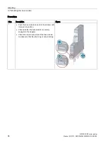
Page 88: ...ed holes please refer to the relevant dimension drawings in the chapter Dimension drawings Page 149 Two screws to fit the holes M4 x 12 in accordance with DIN 784 Two plastic securing brackets Refer to the accessories list for the relevant article number in the chapter Accessories and article number scheme Page 47 Procedure Step Operating instruction Figure 1 Insert the securing brackets into the ...

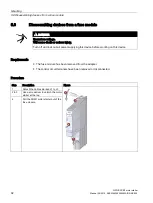
Page 89: ...ANGER Hazardous voltage Will cause death or serious injury Turn off and lock out all power supplying this device before working on this device Requirements The terminals have been removed or disconnected Procedure Step Operating instruction Figure 1 Hold the device firmly 2 Unscrew the cap screws 3 Lift the device from the level surface 4 Remove the securing brackets from the device ...

Page 90: ...e installation location a horizontal 35 mm mounting rail in accordance with DIN EN 60715 is properly secured Please observe the information about the mounting position in chapter Mounting position Page 63 Procedure Step Operating instruction Figure 1 Hang the back of the device onto the upper edge of the standard mounting rail 2 Press the lower half of the device against the rail until the device ...

Page 91: ...s Make sure the rated operational current of the fuses fitted in the module is less than 25 A Procedure Step Description Figure 1 and 2 Push the 3RM1 motor starters into the fuse module until the upper and lower latches on the motor starter enclosure snap into position Pull the device gently to check that it is firmly seated See also Connecting the fuse module option Page 124 ...

Page 92: ...r serious injury Turn off and lock out all power supplying this device before working on this device Requirements The fuse module has been removed from the adapter The control circuit terminals have been removed or disconnected Procedure Step Description Figure 1 Detach the cables marked L1 to L3 2 to 3 Use a screwdriver to unlatch the motor starter at the top 4 Pull the 3RM1 motor starter out of ...

Page 93: ...7 Mounting the fuse module There are two possible mounting positions for the fuse module motor starter assembly Motor feeder at bottom Motor feeder at top Requirements The fuses have been fitted in the fuse module The cover over the fuse compartment is closed The motor starter has been installed and connected up ...

Page 94: ...85095020A RS AE 005 Procedure Step Description Figure 1 Push the fuse module down onto the adapter until it snaps into position Check whether the fuse module is securely engaged in the adapter Check the lower narrow side of the fuse module to make sure that the plastic lug is not protruding ...

Page 95: ... Will cause death or serious injury Turn off and lock out all power supplying this device before working on this device Requirements The control circuit terminals have been removed or disconnected Procedure Step Description Figure 1 and 2 1 Use a screwdriver to press down the plastic lug on the narrow side of the fuse module 2 Pull the module upwards out of the adapter ...

Page 96: ...ole connection Requirements The fuse module has been detached from the busbar system The fuse compartment is open and the fuses removed from the compartment Replacing the fuses in the 3RM19 fuse module Page 137 Procedure Note Modify the fuse module before you install it Step Description Figure 1 Use a pair of pliers to remove the snap rings at phases L2 and L3 Bottom Top ...

Page 97: ...2016 A5E0345285095020A RS AE 005 97 Step Description Figure 2 1 Pick up each of the fuse holders 2 Pull each of the leads with the fuse holder facing inwards out of the housing 3 Insert the fuse into the fuse holder at phase 1 4 Close the fuse compartment 5 Mount the motor starter on the fuse module ...

Page 98: ...rdous voltage Will cause death or serious injury Turn off and lock out all power supplying this device before working on this device Requirements The terminals have been removed or disconnected Procedure Step Operating instruction Figure 1 Press the device downwards 2 Pull the lower half of the device away from the standard mounting rail 3 Lift the device from the upper edge of the standard mounti...

Page 99: ...n a horizontal 35 mm mounting rail in accordance with DIN EN 60715 is properly secured Please observe the information about the mounting position in chapter Mounting position Page 63 Procedure Step Operating instruction Figure 1 Place the back of the device connector on the upper edge of the standard mounting rail 2 Press the lower half of the device connector against the standard mounting rail un...

Page 100: ...r starter 100 Manual 06 2016 A5E0345285095020A RS AE 005 Step Operating instruction Figure 4 Push the device connectors together until they engage 5 Mount the cover on the left on the first device connector in the system configuration The cover is included in the scope of supply of the device terminator ...

Page 101: ...IUS 3RM1 motor starter Manual 06 2016 A5E0345285095020A RS AE 005 101 Step Operating instruction Figure 6 Mount the device on the device connector 7 Mount all the devices required for the system configuration in accordance with the respective installation guidelines on the device connectors ...

Page 102: ...om a standard mounting rail DANGER Hazardous voltage Will cause death or serious injury Turn off and lock out all power supplying this device before working on this device Requirements The terminals have been removed or disconnected Procedure Step Operating instruction Figure 1 Unlock the device using a screwdriver 2 Pull the lower half of the device away from the device connector 3 Unlock the dev...

Page 103: ...ounting rail SIRIUS 3RM1 motor starter Manual 06 2016 A5E0345285095020A RS AE 005 103 Step Operating instruction Figure 4 Pull the device away from the device connector 5 Separate the device connectors using a screwdriver 6 Remove the cover to the left of the first device connector ...

Page 104: ...IUS 3RM1 motor starter 104 Manual 06 2016 A5E0345285095020A RS AE 005 Step Operating instruction Figure 7 Press the device connector down 8 Pull the lower half of the device connector away from the standard mounting rail 9 Lift the device connector from the upper edge of the standard mounting rail ...

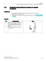
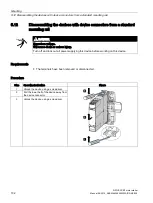
Page 105: ... plug on the level surface For details of the distances between the drilled holes please refer to the relevant dimension drawings in the chapter Dimension drawings Page 149 Two screws to fit the M4 x 12 holes in accordance with DIN 784 Device connector Refer to the accessories list for the relevant article number in the chapter Accessories and article number scheme Page 47 Procedure Step Operating...

Page 106: ...ainst the level surface prepared for screw fastening 4 Insert the screws through the holes in the device connectors 5 Screw the device connector securely onto the level surface Tightening torques Top 0 1 Nm Bottom 1 Nm 6 Mount the device on the device connector 7 Mount all the devices required for the system configuration in accordance with the respective installation guidelines on the device conn...

Page 107: ...ER Hazardous voltage Will cause death or serious injury Turn off and lock out all power supplying this device before working on this device Requirements The terminals have been removed or disconnected Procedure Step Operating instruction Figure 1 Unlock the device on the underside using a screwdriver 2 Pull the lower half of the device away from the device connector 3 Unlock the device on the top ...

Page 108: ...ll SIRIUS 3RM1 motor starter 108 Manual 06 2016 A5E0345285095020A RS AE 005 Step Operating instruction Figure 4 Pull the device away from the device connector 5 Release the screws 6 Separate the device connectors 7 Remove the cover to the left of the first device connector ...

Page 109: ...he sealable cover is used to protect the set rated operational current of the load current setting Ie against unauthorized or unintentional manipulation Procedure Step Operating instruction Figure 1 Attach the two bottom hooks on the cover to the openings on the device and fold the cover up 2 Seal the cover to secure it against unauthorized removal ...

Page 110: ...Mounting 5 15 Mounting the sealable cover SIRIUS 3RM1 motor starter 110 Manual 06 2016 A5E0345285095020A RS AE 005 ...

Page 111: ...signment For optimum response in the event of short circuits and for protection against overvoltages the main circuit s infeed must be at terminals 1 L1 to 5 L3 Requirements Cross tip screwdriver size PZ 1 x 80 For suitable connection cross sections of the cables see chapter Connection cross sections Page 141 Procedure DANGER Hazardous voltage Will cause death or serious injury To ensure protectio...

Page 112: ... 06 2016 A5E0345285095020A RS AE 005 Step Operating instruction Figure 1 Insert the relevant cable into square on the screw terminal until it engages 2 Hold the cable in the screw terminal 3 Tighten the screw with a torque of 0 6 to 0 8 Nm 4 Pull on the cable to ensure it is screwed tight ...

Page 113: ...type terminals DANGER Hazardous voltage Will cause death or serious injury Turn off and lock out all power supplying this device before working on this device Requirements Cross tip screwdriver size PZ 1 x 80 Procedure Step Operating instruction Figure 1 Unscrew the screw of the screw type terminal 2 Remove the cable from the unscrewed screw type terminal ...

Page 114: ... sleeves according to DIN 46228 4 with plastic sleeve 10 mm 1 AWG American Wire Gauge AWG does not define use of end sleeves 2 When 2 x 1 0 mm end sleeves with a plastic sleeve are used space problems may arise with the sleeves as an alternative you are advised to use end sleeves without plastic sleeves Notes on handling spring loaded terminals with push in technology The terminal area of the spri...

Page 115: ...ng this device before working on this device NOTICE Damage to property due to loss of overvoltage protection if wiring is wrong Observe the wiring s terminal assignment For optimum response in the event of short circuits and for protection against overvoltages the main circuit s infeed must be at terminals 1 L1 to 5 L3 Push in connections are a form of spring loaded terminals allowing wiring witho...

Page 116: ...g instruction Figure 1 Insert the cable into the oval opening as far as it will go 2 Pull on the cable to ensure it is tight Table 6 2 Finely stranded conductors Step Operating instruction Figure 1 Insert the screwdriver in the rectangular opening to open the terminal oval opening 2 Insert the cable as far as it will go into the oval opening and remove the screwdriver 3 Pull on the cable to ensure...

Page 117: ...l cause death or serious injury Turn off and lock out all power supplying this device before working on this device Requirements Screwdriver DIN 5264 of the size 0 5 x 3 mm Procedure Step Operating instruction Figure 1 Insert the flat head screwdriver into the rectangular opening of the spring loaded terminal until it engages 2 Remove the cable from the oval opening 3 Remove the screwdriver ...

Page 118: ...ill cause death or serious injury Turn off and lock out all power supplying this device before working on this device Requirements You must have removed the terminals for the purpose of replacing a device for example Procedure Step Operating instruction Figure 1 Insert the terminal into the guide rail of the device 2 Slide the terminal back until it audibly engages ...

Page 119: ...inals DANGER Hazardous voltage Will cause death or serious injury Turn off and lock out all power supplying this device before working on this device Procedure Step Operating instruction Figure 1 Press the clip of the terminal block upwards 2 Pull the terminal out to the front 3 Lift the terminal out of the guide rail of the device ...

Page 120: ...starter 120 Manual 06 2016 A5E0345285095020A RS AE 005 Terminal coding You can provide the terminals with coding pins 3ZY1440 1AA00 These help you to avoid errors when replacing the terminals Figure 6 1 Safety with terminal coding Figure 6 2 Terminal coding ...

Page 121: ...Please note the following requirements for mounting the 3RM19 infeed system Make sure the rated operational current of the infeed system IEC 25 A UL 16 A is not exceeded The 3RM1 motor starters are mounted next to each other on a mounting rail or a level mounting surface The mounting system is only suitable for main current terminals with screw connections Cross tip screwdriver size PZ 1 x 80 For ...

Page 122: ...ystem DANGER Hazardous voltage Will cause death or serious injury If free and uncovered terminal lugs are touched when the load voltage is switched on death or serious physical injury will result For this reason always cover the free terminal lugs free slots that are unassigned for thermal reasons for example with a cover cap The cover caps are available as accessories ...

Page 123: ...rom Step 1 5 Mount the second busbar rotated through 180 The first three terminal lugs overlap here with the last three terminal lugs of the first busbar and are mounted in the same device 4 Tighten the screw terminals with 0 6 to 0 8 Nm Pull on the busbars to ensure they are screwed tight Note Third busbar If you use a third busbar you must rotate it in the same way as the first busbar and mount ...

Page 124: ...wer supplying this device before working on this device Requirements Make sure the rated operational current of the fuses fitted in the module is less than 25 A Procedure Step Description Figure 1 Connect the infeed end of the cables marked L1 to L3 at the 3RM1 motor starter using the connection system provided For further information see the following chapters Connecting the screw type terminals ...

Page 125: ...current setting Ie You set the rated operational current of the load Ie with the rotary coding switch TEST RESET RESET MODE button You can start different function tests with the TEST RESET RESET MODE button You can find details about this in the section Carrying out the function test Page 45 Following an overload trip the 3RM1 motor starter can be reset using the button after three minutes have e...

Page 126: ...TEST RESET RESET MODE button Figure 7 1 Front view of the 3RM1 motor starter 7 1 2 Setting the rated operational current Use a screwdriver to set the load s rated operational current current setting Ie on the rotary coding switch A change takes effect immediately The sealable cover accessory prevents unauthorized access to the rotary coding switch 7 1 3 Setting the RESET method On the 3RM1 motor s...

Page 127: ...lowing an overload trip the machine starts up immediately if there is a control command at IN1 IN2 Personnel in the danger area can be injured Make sure that the danger area of the machine is kept clear of people Note Restriction in the hazardous area In applications for the protection of motors in hazardous areas a 3RM11 3RM13 Failsafe motor starter may only be operated with the Manual RESET sett...

Page 128: ...input direction of rotation 1 IN1 and start input direction of rotation 2 IN2 on 3RM12 and 3RM13 reversing starters only Control circuit fault signaling output 95 96 98 Control circuit signaling output OUT only on Standard motor starters with 24 V DC rated control voltage 3RM10 0 and 3RM12 0 Control circuit RESET input IN3 in the case of 3RM10 3RM12 Standard motor starters Ground inputs M1 M2 in t...

Page 129: ...5285095020A RS AE 005 129 Location of the connections The terminal covers for the control and main circuit are labeled on the inside with the designations of the relevant terminals The position of the label corresponds to the position of the respective terminal Figure 7 3 Upper terminal cover Figure 7 4 Lower terminal cover ...

Page 130: ... 24 V DC Direct on line starter 3RM10 0 IN1 Reversing starter 3RM12 0 IN1 and IN2 110 230 V AC 110 V DC Direct on line starter 3RM10 1 IN1 Reversing starter 3RM12 1 IN1 and IN2 Failsafe 24 V DC Direct on line starter 3RM11 0 IN1 M1 Reversing starter 3RM13 0 IN1 and IN2 M1 and M2 110 230 V AC 110 V DC Direct on line starter 3RM11 1 IN1 Reversing starter 3RM13 1 IN1 and IN2 Main circuit at the botto...

Page 131: ...een RESET MODE Green 7 2 1 2 Status indicators of the 3RM1 motor starter The 3RM1 motor starter indicates the status messages for operation fault and test via the LEDs Operation LED Fault signaling output Reaction of feedback circuit Device status operating mode DEVICE FAILURE STATE RESET MODE Green Off Off Green off Control supply voltage A1 A2 present Motor off No fault Green Off Green Green off...

Page 132: ...ing red Red Off Green off Active Active Malfunction For information about correcting faults please refer to the section Fault rectification Page 134 depending on the selected RESET MODE Note Difference between Standard and Failsafe 3RM11 Failsafe and 3RM13 Failsafe motor starters signal a phase failure immediately 3RM10 and 3RM12 Standard motor starters signal a phase failure after 5 s Test LED Fa...

Page 133: ...ote Behavior in the event of a safety related shutdown The fault signaling output resumes its original state in the event of a safety related shutdown via the control supply voltage Feedback output The Standard motor starters with a control voltage of 24 V DC 3RM10 AA0 and 3RM12 AA0 have a feedback output OUT Run referred to M A2 that outputs a high level when the motor is in operation Since the c...

Page 134: ...n Can cause death or serious injury Check the safety function after acknowledging a disruption in the case of 3RM11 3RM13 Failsafe motor starters Note If a malfunction is repeatedly indicated the 3RM1 motor starter is defective and must be replaced Other faults You acknowledge all other faults using the TEST RESET RESET MODE button As an alternative in the case of the 3RM10 3RM12 Standard motor st...

Page 135: ...n about the status indicators of the 3RM1 motor starter in the chapter Alarms faults and system events Page 131 8 2 Test interval for safety related applications WARNING Loss of the safety function In continuous operation the key safety values apply in the case of a function test interval state change of the outputs 1 year Annual function test Actuate the connected sensors Check their effect on th...

Page 136: ...gh changes to the system Can cause death or serious injury To ensure the safety of the system a complete function test on the system must be conducted and successfully completed following any modifications to the system or replacement of defective components such as 3RM11 and 3RM13 Failsafe motor starters Note A defective device must only be replaced with a device that has exactly the same article...

Page 137: ...fective device must only be replaced with a device that has exactly the same article number Note Example involving replacement of motor starter The example described here involves replacement of the motor starter If the motor starter has appropriate fuse protection it might be fully functional and need not necessarily be replaced Step Operating instruction Figure 1 Remove the 3RM19 fuse module fro...

Page 138: ...ve the defective fuses from the fuse compartment Use a pair of pliers to insert new fuses of an identical type 2 Close the fuse compartment 3 Install and connect up the motor starter again 4 Place the fuse module on the adapter again For further information about dismantling and installation procedures see the following chapters Disassembling devices from a fuse module Page 92 Dismantling the fuse...

Page 139: ...sition vertical horizontal standing Installation altitude at height above sea level maximum 4 000 m 2 000 m Ambient temperature during operation 25 60 C during storage 40 70 C during transport 40 70 C Relative humidity during operation 10 95 Protection against electrical shock finger safe Protection class IP IP20 Note the following Table 3 1 Motor starter version Page 29 Table 3 2 Current ranges P...

Page 140: ...overage level DCavg 99 Function test interval maximum y 1 Diagnostics test interval by internal test function maximum s 600 Failure rate FIT at rate of recognizable hazardous failures λdd FIT 1 400 Failure rate FIT at rate of non recognizable hazardous failures λdu FIT 16 Off delay time with safety related request when switched off via control inputs maximum ms 65 Off delay time with safety relate...

Page 141: ...g contacts auxiliary contacts and for the main circuit main contacts Order number 3RM1 0 1AA 4 3RM1 0 2AA 4 3RM1 0 3AA 4 Type of connectable conductor cross sections for main contacts solid 1x 0 5 4 mm 2x 0 5 2 5 mm 1x 0 5 4 mm 1x 0 5 4 mm 2x 0 5 2 5 mm finely stranded with core end processing 1x 0 5 2 5 mm 2x 0 5 1 5 mm 1x 0 5 2 5 mm 1x 0 5 2 5 mm 2x 0 5 1 5 mm without core end processing 1x 0 5 ...

Page 142: ...feed terminal 3RM19 Order number 3RM1920 1AA Product designation Infeed terminal Type of connectable conductor cross sections for main contacts solid 1x 1 5 4 mm 2x 1 5 2 5 mm finely stranded with core end processing 1x 1 5 2 5 mm 2x 1 5 mm without core end processing at AWG conductors for main contacts 1x 16 12 2x 16 14 ...

Page 143: ...he Siemens Industry Online Support https support industry siemens com cs ww en ps 16311 td 1 Enter the full article number of the desired device in the Product field and confirm with the Enter key 2 Click the Technical data link Overview tables technical data You will find overview tables with technical data in the Product information tab in our online ordering system https mall industry siemens c...

Page 144: ...d the motor starter s actual performance can be higher Motor starter 3RM1 07 3RM1 02 3RM1 01 Unit Max rated operating current Ie 7 A 2 A 0 5 A Motor Starting current Starting time 250 100 ms 1000 3300 3600 1 h 400 100 ms 1000 1000 1000 1 h 400 300 ms 400 400 400 1 h 400 500 ms 220 220 220 1 h 500 100 ms 750 750 750 1 h 500 300 ms 250 250 250 1 h 500 500 ms 150 150 150 1 h 600 100 ms 500 500 500 1 ...

Page 145: ...l 06 2016 A5E0345285095020A RS AE 005 145 9 7 Overload protection device protection characteristic Overload protection Figure 9 1 Motor overload protection characteristic Device protection against overload trips at current setting values from 4 6 A This results in shorter tripping times see figure below ...

Page 146: ...that in the case of 3RM1 motor starters with a rated operational current of 7 A an overload trip may occur in the upper current range before the motor protection trips If for example 8 fold current flows in the case of an unloaded motor memory model and a set current of 7 A tripping takes place after approximately one second Device protection 7 A Device protection 6 1 A Device protection 5 2 A Dev...

Page 147: ...E0345285095020A RS AE 005 147 Resistive loads The tripping characteristic shown does not apply for resistive loads at a setting value of 10 A In this case tripping takes place as follows Table 9 1 Tripping for resistive loads at a setting value of 10 A Tripping after 10 A load current 15 A 20 s Load current 15 A 1 s ...

Page 148: ...Technical data 9 7 Overload protection device protection characteristic SIRIUS 3RM1 motor starter 148 Manual 06 2016 A5E0345285095020A RS AE 005 ...

Page 149: ...mension drawings 10 10 1 CAx data You can find the CAx data in the Siemens Industry Online Support https support industry siemens com cs ww en ps 1 Enter the full article number of the desired device in the Product field and confirm with the Enter key 2 Click the CAx data link ...

Page 150: ...ension drawings for 3RM1 device connectors SIRIUS 3RM1 motor starter 150 Manual 06 2016 A5E0345285095020A RS AE 005 10 2 Dimension drawings for 3RM1 device connectors Dimension drawing of device connectors for 3RM1 motor starter ...

Page 151: ...on drawings 10 2 Dimension drawings for 3RM1 device connectors SIRIUS 3RM1 motor starter Manual 06 2016 A5E0345285095020A RS AE 005 151 Dimension drawing of device termination connectors for 3RM1 motor starter ...

Page 152: ...mension drawings 10 2 Dimension drawings for 3RM1 device connectors SIRIUS 3RM1 motor starter 152 Manual 06 2016 A5E0345285095020A RS AE 005 Dimension drawing of device connectors for signal loop through ...

Page 153: ...Dimension drawings 10 2 Dimension drawings for 3RM1 device connectors SIRIUS 3RM1 motor starter Manual 06 2016 A5E0345285095020A RS AE 005 153 Drilling diagram for device connectors with 22 mm width ...

Page 154: ...Dimension drawings 10 3 3RM1 dimension drawings SIRIUS 3RM1 motor starter 154 Manual 06 2016 A5E0345285095020A RS AE 005 10 3 3RM1 dimension drawings Dimension drawing for 3RM1 motor starter ...

Page 155: ...Dimension drawings 10 3 3RM1 dimension drawings SIRIUS 3RM1 motor starter Manual 06 2016 A5E0345285095020A RS AE 005 155 Drilling diagram for push in lugs for wall mounting ...

Page 156: ...Dimension drawings 10 3 3RM1 dimension drawings SIRIUS 3RM1 motor starter 156 Manual 06 2016 A5E0345285095020A RS AE 005 Dimension drawing for 3RM1 motor starter with infeed terminal and system ...

Page 157: ...S 3RM1 motor starter Manual 06 2016 A5E0345285095020A RS AE 005 157 10 4 Dimension drawings 3RM19 fuse module Dimension drawing of the fuse module with 3RM1 motor starter See also Siemens Industry Online Support https support industry siemens com cs ww en ps 16311 td ...

Page 158: ...Dimension drawings 10 4 Dimension drawings 3RM19 fuse module SIRIUS 3RM1 motor starter 158 Manual 06 2016 A5E0345285095020A RS AE 005 ...

Page 159: ...ircuit diagrams 11 11 1 CAx data You can find the CAx data in the Siemens Industry Online Support https support industry siemens com cs ww en ps 1 Enter the full article number of the desired device in the Product field and confirm with the Enter key 2 Click the CAx data link ...

Page 160: ...ine starter Standard SIRIUS 3RM1 motor starter 160 Manual 06 2016 A5E0345285095020A RS AE 005 11 2 3RM10 circuit diagrams direct on line starter Standard Versions with 24 V DC control supply voltage Versions with 110 230 V AC 110 V DC control supply voltage ...

Page 161: ...arter Manual 06 2016 A5E0345285095020A RS AE 005 161 Note Parallel loads in the case of motor starters with product version E01 In the case of motor starters with product version E01 no parallel loads can be connected to the IN terminal see diagram below This is admissible as of product version E02 ...

Page 162: ...ine starter Failsafe SIRIUS 3RM1 motor starter 162 Manual 06 2016 A5E0345285095020A RS AE 005 11 3 3RM11 circuit diagrams direct on line starter Failsafe Versions with 24 V DC control supply voltage Versions with 110 230 V AC 110 V DC control supply voltage ...

Page 163: ...ing starter Standard SIRIUS 3RM1 motor starter Manual 06 2016 A5E0345285095020A RS AE 005 163 11 4 3RM12 circuit diagrams reversing starter Standard Versions with 24 V DC control supply voltage Versions with 110 230 V AC 110 V DC control supply voltage ...

Page 164: ...er 164 Manual 06 2016 A5E0345285095020A RS AE 005 Note Parallel loads in the case of motor starters with product version E01 In the case of motor starters with product version E01 no parallel loads can be connected to the IN terminal see diagram below This is admissible as of product version E02 ...

Page 165: ...ing starter Failsafe SIRIUS 3RM1 motor starter Manual 06 2016 A5E0345285095020A RS AE 005 165 11 5 3RM13 circuit diagrams reversing starter Failsafe Versions with 24 V DC control supply voltage Versions with 110 230 V AC 110 V DC control supply voltage ...

Page 166: ...Circuit diagrams 11 5 3RM13 circuit diagrams reversing starter Failsafe SIRIUS 3RM1 motor starter 166 Manual 06 2016 A5E0345285095020A RS AE 005 ...

Page 167: ...1 Typical circuits for 3RM1 A 1 1 Direct on line starter 24 V DC with switch operation The 3RM1 motor starter is controlled with a switch The 3RM1 motor starter is operated as a direct on line starter S1 ON S2 Remote reset Figure A 1 Standard 24 V DC direct on line starter with switch operation ...

Page 168: ...t for the brake facility is drawn via only one phase Connection is via T2 Note This configuration is admissible for standard variants 3RM10 and 3RM12 only This operating mode is not suitable for 3RM11 Failsafe and 3RM13 Failsafe motor starters since there is a connection to the neutral conductor S1 ON S2 Remote reset Figure A 2 Standard 24 V DC direct on line starter with switch operation and 230 ...

Page 169: ...ases Connection is via T1 and T3 Make allowance for the additional current in the current setting value The configuration is shown based on the example of a standard motor starter The configuration with a 400 V brake is also admissible for the Failsafe variants 3RM11 and 3RM13 The notes on safety related shutdown Page 174 must be observed S1 ON S2 Remote reset Figure A 3 Standard 24 V DC direct on...

Page 170: ...guration for single phase loads is also admissible for the Failsafe variants 3RM11 and 3RM13 The notes on safety related shutdown Page 174 must be observed NOTICE Damage to property can occur Connection IN2 on reversing starters must not be used in the case of single phase motors NOTICE Damage to property due to high making currents When using capacitive loads the switching components in the 3RM1 ...

Page 171: ... S2 Remote reset Figure A 4 Standard direct on line starter 24 V DC with switch operation and single phase motor A 1 5 Direct on line starter with group protection 24 V DC and PLC operation Several 3RM1 motor starters can be connected by means of 3 phase busbars on the main current side Control takes place via digital outputs ...

Page 172: ... configuration is shown based on the example of standard motor starters In the main circuit this configuration is also admissible for the Failsafe variants 3RM11 and 3RM13 The notes on safety related shutdown Page 174 must be observed Figure A 5 Standard direct on line starter with group protection 24 V DC and PLC operation ...

Page 173: ... motor starter Manual 06 2016 A5E0345285095020A RS AE 005 173 A 1 6 Reversing starter 24 V DC with PLC operation The motor is controlled via a PLC The 3RM1 motor starter is operated as a reversing starter Figure A 6 Reversing starter 24 V DC with PLC operation ...

Page 174: ...motor Will cause death serious injury or damage to property Health hazard from automatic hot restart The safety function must be checked after every tripping of the motor starter protector also in the case of overload After every short circuit in the case of short circuit protection according to type of coordination 1 a 3RM1 motor starter is defective Replace a 3RM1 motor starter including the ter...

Page 175: ... starters with 110 to 230 V AC control supply voltage must come from A1 Otherwise the safety function is bypassed in the event of a fault Thus only relay outputs are admissible when using a PLC Do not use a separate control voltage Only use the relay outputs when using a PLC WARNING Loss of the safety function when using device connectors Can cause death or serious injury When the product is opera...

Page 176: ...detailed information about safe functional extra low voltage in the data sheets of the power supplies to be used WARNING Loss of the safety function when the neutral conductor is connected to a load Can cause death or serious injury When using the 3RM11 Failsafe and 3RM13 Failsafe motor starters note that no neutral conductor may be connected if the load circuit contains 3 phase loads e g a 230 V ...

Page 177: ... IN2 e g with a PLC The control supply voltage L and L to the motor starters is deactivated by the 3SK1 safety relay and the system is in a safe state Note SILCL 3 in accordance with EN 62061 PL e in accordance with EN ISO 13849 1 A safety related application up to SILCL 3 to EN 62061 PL e Cat 4 to EN ISO 13849 1 can be realized in this way To achieve SILCL 3 PL e Cat 4 for the safety related appl...

Page 178: ... 06 2016 A5E0345285095020A RS AE 005 If there is a common reference potential for the two inputs it is sufficient to establish a ground connection If there are separate potentials or controls both connections must be assigned Figure A 7 3SK1 safety relay with 3RM13 reversing starter via device connector ...

Page 179: ...arters with 110 to 230 V AC control supply voltage must come from A1 Otherwise the safety function is bypassed in the event of a fault Thus only relay outputs are admissible when using a PLC Do not use a separate control voltage Only use the relay outputs when using a PLC The control supply voltage L1 and N to the motor starters is deactivated by the 3SK1 safety relay and the system is in a safe s...

Page 180: ...Typical circuits A 2 Typical circuits for safety related shutdown SIRIUS 3RM1 motor starter 180 Manual 06 2016 A5E0345285095020A RS AE 005 Figure A 8 3SK1 safety relay with 3RM13 reversing starter ...

Page 181: ... local input IN1 by means of the 3SK2 safety relay WARNING Loss of the safety function when using device connectors Can cause death or serious injury When operating with a 3SK2 safety relay and 3ZY12 device connectors the supply voltage for 3RM1 Failsafe motor starters is established via the 3ZY12 device connectors To prevent bypassing of the safety function do not connect anything to terminals A1...

Page 182: ...via the terminals A1 A2 Safety related switching of the local input of the 3RM1 Failsafe motor starter via fail safe output of the 3SK2 safety relay Suitable for frequently requested safety functions e g on indexing tables No use of device connectors Protected laying of signal cables between the 3SK2 safety relay and 3RM1 Failsafe motor starter in the same control cabinet or in armored conduit Cir...

Page 183: ...e achieved To this end the controlling outputs must also fulfill SILCL3 in accordance with EN 62061 PL e Cat 4 in accordance with EN ISO 13849 1 Note SILCL 3 in accordance with EN 62061 PL e Cat 4 in accordance with EN ISO 13849 1 SILCL 3 in accordance with EN 62061 PL e Cat 4 in accordance with EN ISO 13849 1 can be achieved by laying the control lines from the safe output to IN1 and IN2 of the 3...

Page 184: ...ical circuits A 2 Typical circuits for safety related shutdown SIRIUS 3RM1 motor starter 184 Manual 06 2016 A5E0345285095020A RS AE 005 Figure A 9 3RM13 reversing starter with PLC control F DO pp switching ...

Page 185: ...3 Failsafe motor starters can be controlled by an F DO module In this typical circuit shutdown is realized by a pm switching F DO module in 2 channels Up to SILCL 3 in accordance with EN 62061 PL e Cat 4 in accordance with EN ISO 13849 1 can be achieved To this end the controlling outputs must also fulfill SILCL3 in accordance with EN 62061 PL e Cat 4 in accordance with EN ISO 13849 1 Figure A 10 ...

Page 186: ...Typical circuits A 2 Typical circuits for safety related shutdown SIRIUS 3RM1 motor starter 186 Manual 06 2016 A5E0345285095020A RS AE 005 ...

Page 187: ...ch Electrostatic Sensitive Devices This is also the international abbreviation for such devices ESD modules are identified by the following symbol NOTICE Damage caused by electrostatically charged persons ESD devices can be destroyed by voltages well below the threshold of human perception These static voltages develop when you touch a component or electrical connection of a device without having ...

Page 188: ...r Basic protective measures against electrostatic discharge Ensure good equipotential bonding When handling electrostatic sensitive devices ensure that your body the workplace and the packaging are grounded In this way you can avoid becoming electrostatically charged Avoid direct contact As a general rule only touch electrostatic sensitive devices when this is unavoidable e g during maintenance wo...

Page 189: ... sectional area of a conductor or wire Each AWG number represents a jump of 26 in the cross sectional area The thicker the wire the smaller the AWG number CLASS time See Trip class Connection system The 3RM1 motor starter is connected using screw terminals push in connections and hybrid connection technology Explosion protection Prerequisite for using electrical equipment in hazardous areas confor...

Page 190: ...es and AC 22 for load break switches utilization category 7 Switch position displayed automatically Motor protection Motor protection protects electric motors against thermal overload due to mechanical overload or in the event of failure of a single or two phase s Motor starter protector circuit breaker Generally a latch operated switch that can make carry and break currents in the circuit under n...

Page 191: ... entering a command until the time that the first contact connection is made at the contactor for example The switch on delay is the time between application of the control voltage and the first current flow The switch off delay is the time between removal of the control voltage and interruption of the current flow RoHS EC Directive 2002 95 EC concerning the restriction of the use of certain hazar...

Page 192: ... release trips within a certain time Type of coordination 1 The load feeder may be non operational after a short circuit has been cleared Damage to the 3RM1 motor starter is permissible Type of coordination 2 The 3RM1 motor starter remains functional after a short circuit Types of coordination The IEC 60947 4 1 VDE 0660 Part 102 standard distinguishes between two types of coordination type of coor...

Page 193: ...ata 15 149 159 Certification ATEX 39 Characteristic 12 Characteristics 145 CLASS 10A 57 147 Clearances to be observed 64 Clearances to be observed 64 Compact busbar system 50 81 Compact load feeder 50 Configuration 15 Configurator 15 Conformity 12 Connect fuse module 124 Connecting 36 Connecting lug 79 122 Connection 129 Connection system 29 Connections 130 Control circuit 128 Control current term...

Page 194: ...system 48 80 121 Mounting 80 Infeed terminal 121 Installation altitude 58 Insulation strength Restricted 58 L LED colors 131 LED display 131 LED test 46 Load change stability Maximum 50 Load feeder 29 69 81 Compact 50 IEC 69 UL 73 Loads 25 M Main circuit 79 128 Main circuit wiring 79 Main current terminal 114 Main current terminals 55 Maintenance 41 135 Malfunction 42 134 135 Display concept 43 Ma...

Page 195: ...4 76 84 175 177 179 181 Safety related application Example 83 Safety related shutdown 29 42 43 45 SCCR 73 Screw connection 29 79 121 Screw terminal 112 113 123 Sealable cover 51 126 Sealing 109 Service Support 13 Setting 126 Short circuit 74 76 Short circuit current rating 73 Short circuit protection 26 40 69 72 81 179 Short circuit strength 69 Shutdown 42 Safety related 43 45 Side by side mountin...

Page 196: ...Index SIRIUS 3RM1 motor starter 196 Manual 06 2016 A5E0345285095020A RS AE 005 V Voltage source 30 W Wall mounting 51 Warranty 41 Wiring 111 115 ...

Reviews: