6.6
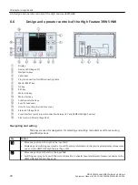
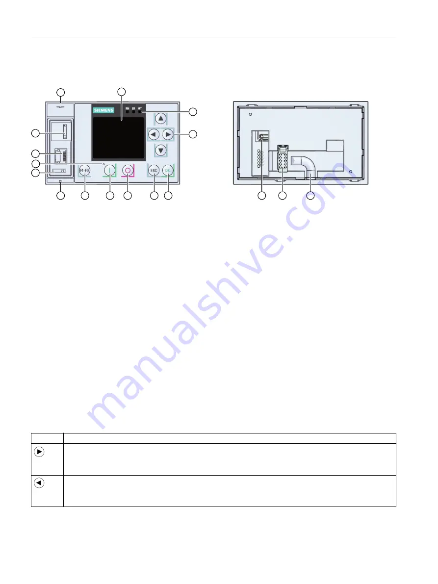
Design and operator controls of the High Feature 3RW5 HMI
①
Display
②
Device LEDs (Page 247)
③
Navigation keys
④
Cable duct
⑤
Plug-in connection for HMI connecting cable
⑥
Master RESET key
⑦
OK key
⑧
ESC key
⑨
Motor stop key
⑩
Motor start key
⑪
Function selection key
⑫
Eyes for lead seals
⑬
Hole for mounting the interface cover
⑭
⑮
Local interface (point-to-point connection between PC and 3RW5 HMI High Feature)
⑯
Slot for micro SD card (Page 243)
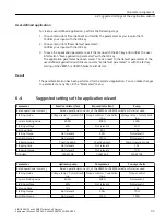
Navigating and setting
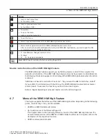
The keys are used for navigation, for selecting and setting menu items and for executing
predefined actions.
Key
Actions
• Move one position to the right in the input field
• Displaying and switching over graphs. You will find more information in chapter Graphical display of measured
values on the 3RW5 HMI High Feature (Page 229).
• Move one position to the left in the input field
• Switching over graphs. You will find more information in chapter Graphical display of measured values on the
3RW5 HMI High Feature (Page 229).
Parameter assignment
6.6 Design and operator controls of the High Feature 3RW5 HMI
SIRIUS 3RW55 and 3RW55 Failsafe Soft Starters
98
Equipment Manual, 02/2022, A5E35630887002A/RS-AF/006

