3RW55 Failsafe soft starter
Digit of the article number
1st-4th
5th
6th
7th
8th
9th
10th
11th
12th
SIRIUS 3RW soft starter
3RW5
5
H
F
Size of the 3RW55 Failsafe soft starter
x*
1)
Rated operational current I
e
of the 3RW55 Failsafe soft starter
x**
1)
Connection system
• Applies to sizes 1/2
• Main circuit: Screw terminals
• Control circuit: Screw terminals
1
• Applies to sizes 3/4
• Main circuit: Bus connection
• Control circuit: Spring-loaded terminals
2
• Applies to sizes 1/2
• Main circuit: Screw terminals
• Control circuit: Spring-loaded terminals
3
• Applies to sizes 3/4
• Main circuit: Bus connection
• Control circuit: Screw terminals
6
Rated control supply voltage U
s
2)
24 V AC/DC
0
110 - 250 V AC
1
Rated operational voltage U
e
200 - 480 V AC
4
1)
Explanation in the following table.
2)
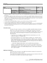
When rating the control supply voltage, pay attention to the maximum starting current when closing the bypass contacts;
details can be found in the technical data.
The following table shows the size and rated operational current I
e
for U
e
= 400 V and TU = 40 °C
in a standard (inline) circuit:
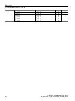
Size
Rated operational current I
e
of
the 3RW55 Failsafe soft starter
Rated operating power P
e
of the 3RW55
Failsafe soft starter
x*
x**
Size 1
I
e
= 13 A
P
e
= 5.5 kW
1
3
I
e
= 18 A
P
e
= 7.5 kW
1
4
I
e
= 25 A
P
e
= 11 kW
1
5
I
e
= 32 A
P
e
= 15 kW
1
6
I
e
= 38 A
P
e
= 18.5 kW
1
7
Size 2
I
e
= 47 A
P
e
= 22 kW
2
4
I
e
= 63 A
P
e
= 30 kW
2
5
I
e
= 77 A
P
e
= 37 kW
2
6
I
e
= 93 A
P
e
= 45 kW
2
7
Size 3
I
e
= 113 A
P
e
= 55 kW
3
4
I
e
= 143 A
P
e
= 75 kW
3
5
I
e
= 171 A
P
e
= 90 kW
3
6
Description
3.10 Structure of the article number
SIRIUS 3RW55 and 3RW55 Failsafe Soft Starters
Equipment Manual, 02/2022, A5E35630887002A/RS-AF/006
47


