5.2
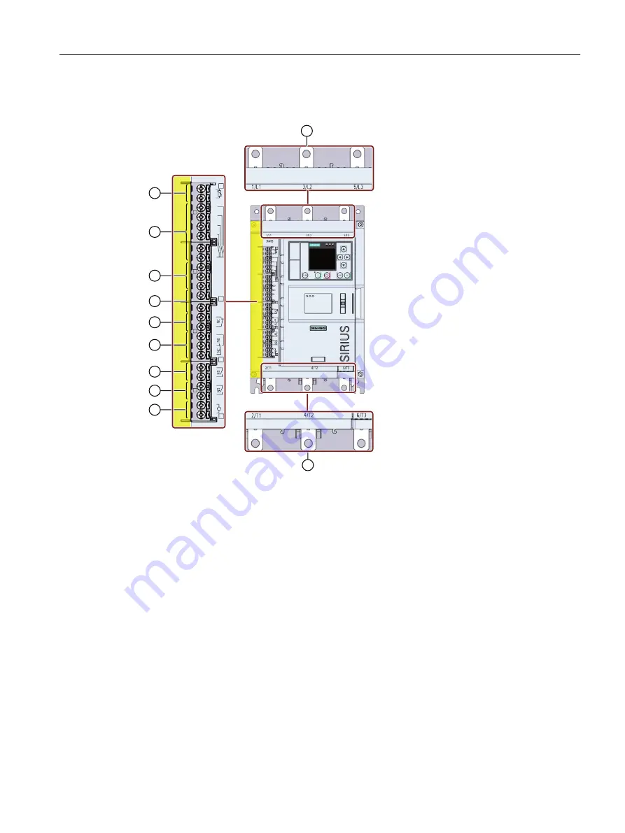
Overview of all connections of the 3RW55 Failsafe soft starter
0
/
$48
$4,
$4
)',
)0
7
7
',
',
',
',
$
$
0
)',
)0
①
Main circuit connection, line side 1/L1, 3/L2, 5/L3
②
Main circuit connection, load (motor) side 2/T1, 4/T2, 6/T3
③
A1 / A2: Supply voltage (control supply voltage) for control terminals (24 V AC/DC or 110 - 250 V
AC)
④
Output 13, 14 (output 1): For signaling operating states and faults (parameterizable (Page 198))
⑤
Output 23, 24 (output 2): For signaling operating states and faults (parameterizable (Page 198))
⑥
Output 95, 96 and 98 (output 3): For signaling faults
⑦
Output 41, 42 (output 4, F‑RQ): Failsafe signaling output (not parameterizable)
⑧
F‑DI: Failsafe digital input (not parameterizable)
F‑M: Failsafe input ground (not parameterizable)
⑨
Analog output AQ-, AQ I+ and AQ U+: For outputting different measured values
• AQ- / AQ U+: For signal type voltage, signal range 0 ... 10 V
• AQ- / AQ I+: For signal type current, signal range 4 - 20 mA
⑩
Control inputs DI1, DI2, DI3, DI4, L+ and M
⑪
Thermistor motor protection T1 and T2: Connection of an optional temperature sensor
Connecting
5.2 Overview of all connections of the 3RW55 Failsafe soft starter
SIRIUS 3RW55 and 3RW55 Failsafe Soft Starters
Equipment Manual, 02/2022, A5E35630887002A/RS-AF/006
73

