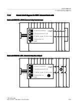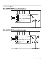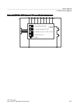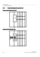
System configuration
6.3 System configuration rules
3SK1 safety relays
100
Manual, 04/2013, A5E02526190021A/RS-AA/01
6.2.2
Applications
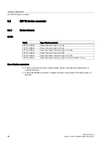
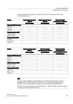
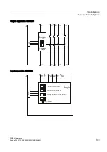
The Advanced basic unit can be expanded on the input and output side using device
connectors (connecting plugs) without any additional wiring outlay. When configuring the
system, it is important to ensure that input expansions are connected on the left and output
expansions on the right of a basic unit.
6.3
System configuration rules
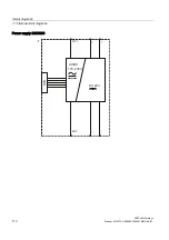
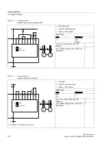
● Input expansions and the 3SK1230 power supply must always be connected on the left of
the basic unit and output expansions on the right.
● The 3SK1230 power supply must always be plugged into the system on the extreme left.
● If a 3SK1230 power supply is used, no additional, external 24 V DC voltage is permitted
to be connected to a basic unit.
● If an input expansion is detected on the left when the device powers up, this will be
loaded into the device configuration. The cascading input image is then activated in
safety mode and ANDed with the sensor states.
● An input expansion evaluates the sensor states and generates an enable signal for the
basic unit depending on the start condition. The enable signal is then acquired by an
input expansion on the right-hand side, or acquired by the basic unit and ANDed with its
sensor statuses.
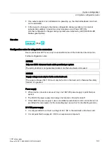
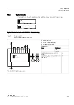
● Device termination connector type 1:
– Below basic unit: the switch of the device termination connector must be open, i.e. in
position 2 at the bottom.
– Below 3SK1211 output expansion: the switch of the device termination connector
must be closed, i.e. in position 1 at top.
● The 3ZY12 device connector used below the final device must be fitted with a cover on
the left side (supplied with the device termination connectors).
● If an output expansion is detected on the right when the device powers up, this will be
loaded into the device configuration. The internal feedback circuit of the contact extension
is evaluated and checked.
● An Advanced basic unit controls the output expansions via the 3ZY12 device connector.
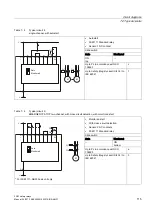
● If an output expansion is used, a device termination connector of type 1 must ALWAYS
be used under the final device on the right (for 3SK1211) with the switch setting: "1"
(switch upwards), or type 2 (for 3SK1213)
● If the 3SK1213 output expansion is used in the system, this must always be the final
station in the system (on the right) and must be fitted with a 3ZY1212-0FA01 device
termination connector. Only one 3SK1213 output expansion can be used in a system with
a device connector.
● The output expansion (instantaneous) is activated via a safety-related channel.
● The output expansion (time-delayed) is activated via a safety-related channel.
● If a basic unit is operated as a stand-alone device, no device connector or device
termination connector is necessary.
Summary of Contents for SIRIUS 3SK1
Page 2: ......
Page 10: ...Table of contents 3SK1 safety relays 10 Manual 04 2013 A5E02526190021A RS AA 01 ...
Page 186: ...Commissioning 3SK1 safety relays 186 Manual 04 2013 A5E02526190021A RS AA 01 ...
Page 258: ...Accessories 3SK1 safety relays 258 Manual 04 2013 A5E02526190021A RS AA 01 ...
Page 260: ...Appendix A 1 Correction sheet 3SK1 safety relays 260 Manual 04 2013 A5E02526190021A RS AA 01 ...
Page 261: ......

