Circuit diagrams
7.2 Typical circuits
3SK1 safety relays
Manual, 04/2013, A5E02526190021A/RS-AA/01
111
7.2
Typical circuits
7.2.1
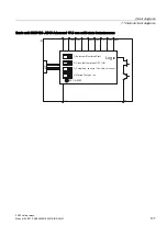
Sensor wiring
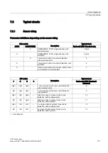
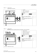
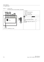
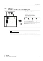
Parameter definitions depending on the sensor wiring
Slide switch
Typical circuit
AUTO
MONITORED
Description
Basic unit 3SK1 Standard relay
X
EMERGENCY STOP, single-channel, with
monitored start
1 and 2
X
EMERGENCY STOP, single-channel, with
autostart
3 and 4
X
Two-channel, with cross-circuit detection,
with monitored start
5
X
Two-channel, with cross-circuit detection, with
autostart
6
X
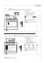
Sensors with solid-state outputs, without cross-
circuit detection, with autostart
7
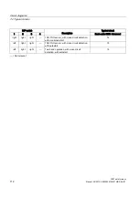
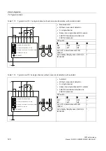
DIP switch
Typical circuit
1
2
3
4
Description
Basic units 3SK1 Standard /
Advanced
right
right
right
—
1 x two-channel, with cross-circuit detection,
with monitored start
8
left
right
right
—
1 x two-channel, with cross-circuit detection
with autostart
9
right
left
right
—
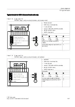
Electronic sensor, without cross-circuit
detection, with monitored start
10
left
left
right
—
Electronic sensor, without cross-circuit
detection, with autostart
11
right
left
left
—
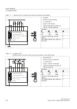
2 x single-channel, without cross-circuit
detection, with monitored start
12
left
left
left
—
2x single-channel, without cross-circuit
detection, with autostart
13
— = Not relevant
Summary of Contents for SIRIUS 3SK1
Page 2: ......
Page 10: ...Table of contents 3SK1 safety relays 10 Manual 04 2013 A5E02526190021A RS AA 01 ...
Page 186: ...Commissioning 3SK1 safety relays 186 Manual 04 2013 A5E02526190021A RS AA 01 ...
Page 258: ...Accessories 3SK1 safety relays 258 Manual 04 2013 A5E02526190021A RS AA 01 ...
Page 260: ...Appendix A 1 Correction sheet 3SK1 safety relays 260 Manual 04 2013 A5E02526190021A RS AA 01 ...
Page 261: ......


