
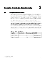

PSU8600power supply systems
___________________
___________________
___________________
___________________
___________________
___________________
___________________
___________________
___________________
___________________
___________________
___________________
___________________
___________________
___________________
SITOP Power Supplies
PSU8600power supply systems
Manual
SITOP PSU8600 24 V DC/20 A/4 x 5 A
6EP3436-8MB00-2CY0
SITOP PSU8600 24 V DC/40 A/4 x 10 A
6EP3437-8MB00-2CY0
SITOP CNX8600 4 x 5 A
6EP4436-8XB00-0CY0
SITOP CNX8600 4 x 10 A
6EP4437-8XB00-0CY0
SITOP BUF8600 100 ms/40 A
6EP4297-8HB00-0XY0
SITOP BUF8600 300 ms/40 A
6EP4297-8HB10-0XY0
SITOP BUF8600 4 s/40 A
6EP4293-8HB00-0XY0
SITOP BUF8600 10 s/40 A
6EP4295-8HB00-0XY0
04.2016
A5E35883207-7-76
Summary of Contents for SITOP BUF8600
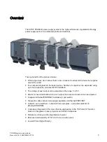
Page 6: ...Overview PSU8600power supply systems 6 Manual 04 2016 A5E35883207 7 76 ...
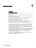
Page 12: ...Safety instructions PSU8600power supply systems 12 Manual 04 2016 A5E35883207 7 76 ...
Page 246: ...Environmental conditions PSU8600power supply systems 246 Manual 04 2016 A5E35883207 7 76 ...
Page 250: ...Environment PSU8600power supply systems 250 Manual 04 2016 A5E35883207 7 76 ...


