Description, device design, dimension drawing
2.3 Potentiometer
SITOP PSU100C
Operating Instructions, 06.2013, C98130-A7599-A1-2-7629
11
2.3
Potentiometer
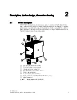
The potentiometer
④
on the front of the device is used to adjust the output voltage. The
output voltage is set to the rated value at the factory and can be set within certain limits; for
example, to compensate voltage drops across long supply lines to the connected load.
Figure 2-3
Potentiometer (example 6EP1332-5BA10)
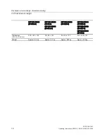
Type
Factory setting
Setting range
6EP1321-5BA00 (12 V/2 A)
6EP1322-5BA10 (12 V/6.5 A)
12 V
10.5...12.9 V
6EP1331-5BA10 (24 V/1.3 A)
6EP1332-5BA00 (24 V/2.5 A)
6EP1332-5BA10 (24 V/4 A)
24 V
22.2...26.4 V
6EP1331-5BA00 (24 V/0.6 A)
6EP1332-5BA20 (24 V/3.7 A)
24 V
-
The following devices do not have a potentiometer: 6EP1331-5BA00 and 6EP1332-5BA20.
NOTICE
Thermal overload possible
When adjusting the output voltage to >24 V or >12 V, the output current must be derated by
4%/V.
Note
It is only permissible to activate the potentiometer using an insulated screwdriver.
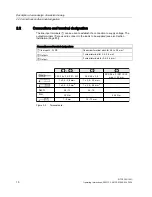
For notes on actuating the potentiometer (screwdriver, torque), see Figure 2-2 Terminal data
(Page 10).


