Description, device design, dimension drawing
2.1 Device description
SITOP SEL1200-1400
10
Manual, 06.2019, A5E46496083-1-76
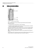
①
+24 V DC input
②
0 V connection for the internal supply
③
+24 V DC outputs
④
Group signaling contact (13, 14); not assigned (NF); remote reset (RST)
⑤
Potentiometer for each output
⑥
(ON/OFF/RST) pushbutton and indicator light for each output
⑦
Selector switch for diagnostic interface (COM)
⑧
Selector switch for switch-in delay (time definition) (TD1, TD2)
⑨
Mounting rail slider
⑩
Natural convection
⑪
Clearance above/below
Figure 2-1
Design
Summary of Contents for SITOP SEL1200
Page 8: ...Safety instructions SITOP SEL1200 1400 8 Manual 06 2019 A5E46496083 1 76 ...
Page 26: ...Mounting removal SITOP SEL1200 1400 26 Manual 06 2019 A5E46496083 1 76 ...
Page 46: ...Safety approvals EMC 7 3 EMC SITOP SEL1200 1400 46 Manual 06 2019 A5E46496083 1 76 ...
Page 48: ...Ambient conditions SITOP SEL1200 1400 48 Manual 06 2019 A5E46496083 1 76 ...
Page 50: ...Environment SITOP SEL1200 1400 50 Manual 06 2019 A5E46496083 1 76 ...


