Description, device design, dimension drawing
2.7 Setting the switch-on delay time
SITOP SEL1200-1400
Manual, 06.2019, A5E46496083-1-76
21
2.7
Setting the switch-on delay time
For specific loads, it can make sense to sequentially switch-on the outputs in order to reduce
the peak inrush currents, and therefore the load on the power supply. To achieve this, the
individual outputs of the selectivity module can be switched-in with a time delay between one
another in a fixed sequence (output 1 ⇒ 2 ⇒ 3 ⇒ 4 ⇒ 5 ⇒ 6 ⇒ 7 ⇒ 8). The delay time set
between the individual outputs is the same for all of the outputs. The delivery condition is
load-dependent switch on.
Setting the sequential switch-on delay
Figure 2-8
Selector switch
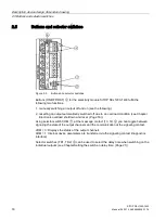
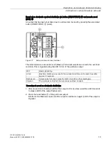
The switch-on delay time is set at selector switches TD1 and TD2
⑧
. When delivered, DIP
switches "TD1" and "TD2" are in the "0" position (load-dependent switch on delay).
Procedure when setting the delay time:
With the selectivity module in a no-voltage condition, set DIP switches "TD1" and "TD2" to
the required delay time.
Outputs switched on depending on the load: The next output is switched on as soon as the
previous output has run-up (at the earliest, after 5 ms).
25 ms delay between the outputs being switched on
200 ms delay between the outputs being switched on
500 ms delay between the outputs being switched on
The next time that the selectivity module powers up, the outputs are sequentially switched on
corresponding to the selected delay time.
Summary of Contents for SITOP SEL1200
Page 8: ...Safety instructions SITOP SEL1200 1400 8 Manual 06 2019 A5E46496083 1 76 ...
Page 26: ...Mounting removal SITOP SEL1200 1400 26 Manual 06 2019 A5E46496083 1 76 ...
Page 46: ...Safety approvals EMC 7 3 EMC SITOP SEL1200 1400 46 Manual 06 2019 A5E46496083 1 76 ...
Page 48: ...Ambient conditions SITOP SEL1200 1400 48 Manual 06 2019 A5E46496083 1 76 ...
Page 50: ...Environment SITOP SEL1200 1400 50 Manual 06 2019 A5E46496083 1 76 ...


