FEC920: USER GUIDE
Page 100
September 18
6.9 DIGITAL I/O
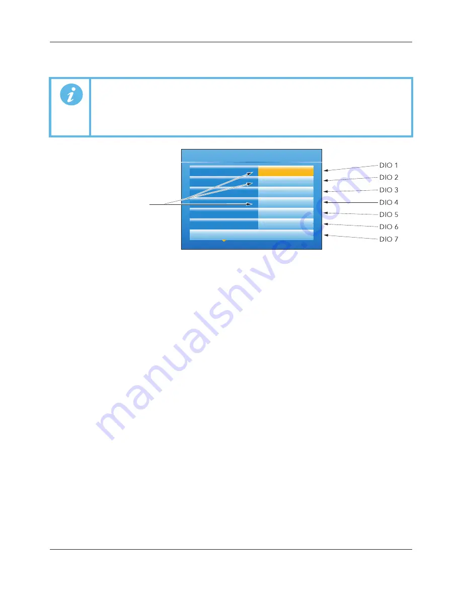
This area of configuration allows the digital I/O types to be selected.
Figure 89 Digital I/O top level menu
6.9.1 Digital input/output
This applies to signals at terminals 1A/1B (Figure 4). Highlight ‘1A1B’, then operate the scroll key to reveal the
configuration menu.
Module Ident
Dig IO
Type
On Off O/P, Time Prop O/P or Contact I/P (default)
PV
For inputs, 0 = contact is open; 1 = contact is closed. For On Off O/P, a value
0.5 drives
the output high, otherwise, the output is driven low. For Time Prop O/P, the value is the
demanded output percentage.
Min On Time
For Type = Time Prop O/P only, this allows a minimum on time to be specified.
Configurable range = 0.1 to 150 seconds
Invert
Inverts the output sense for digital outputs; or the input signal for digital inputs.
Output
Off = output being driven low; On = output being driven high. Does not appear for Type =
Contact I/P
6.9.2 Relay outputs
This may apply to terminal pairs 1A1B, 2A2B, 3A3B, 4AC, 5AC (Figure 4). Highlight the relevant terminal pair,
then operate the scroll key to reveal the configuration menu.
Module Ident
Relay.
Type (2A2B, 4AC)
‘On Off O/P’ (default), Time Prop O/P, Valve Raise (not if DC output I/O fitted).
Type (3A3B, 5AC)
‘On Off O/P’ (default), ‘Time Prop O/P’. The 3A3B relay is not fitted if ‘DC Output’ I/O is
fitted (see Section 6.10.1).
PV
For On Off O/P, a value
0.5 closes the relay contacts, otherwise, the contacts are open.
For Time Prop O/P, the value is the demanded output percentage.
Min On Time
For Type = Time Prop O/P only, this allows a minimum on time to be specified to reduce
relay wear. Configurable range = 0.1 to 150 seconds.
Invert
Inverts the output sense for the relays (not applicable if Type = Valve Raise).
Inertia
For Type = Valve Raise only, this allows a value to be entered (in seconds) to take into
account valve run-on.
Backlash
For Type = Valve Raise only, this allows a value to be entered (in seconds) in order to
compensate for backlash in the valve linkage.
Note:
If 2A2B is set to ‘Valve Raise’, then 3A3B is set to ‘Valve Lower’. Similarly, if relay 4AC is set
to ‘Valve Raise’, then relay 5AC is set to ‘Valve Lower’.
When the loop channel output is wired to the PV input of a Valve Raise function, then the PV
input of the associated Valve Lower function becomes unavailable for wiring, and both
outputs are controlled by the loop as a pair, using only the single wire.
Instrument
Network
Group
Channel
Virtual Channel
Loop
Digital I/O
Select configuration menu
:
Note: These fields do not appear if
they contain I/O type ‘DC Output’.
1A1B
2A2B
LALC (Dig.In)
3A3B
LBLC (Dig.In)
4AC (Relay)
5AC (Relay)
A5E45696052A Rev-AA


