FEC920: USER GUIDE
Page 9
A
September 18
4 INSTALLATION
4.1 MECHANICAL INSTALLATION
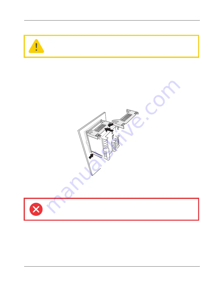
Figure 1 gives installation details.
4.1.1 Installation Procedure
1.
If it is not already in place, fit the IP65 sealing gasket behind the front bezel of the instrument.
2.
Insert the instrument through the panel cutout, from the front of the panel.
3.
Spring the retaining clips into place, and secure the instrument by holding it firmly in place whilst pushing
both clips towards the rear face of the panel.
4.
The protective membrane can now be removed from the display.
Figure 1 Securing the Instrument
4.1.2 Demounting
1.
Isolate the mains supply and secure it against accidental operation. Remove all wiring and the USB
device and Ethernet cable (if any).
2.
Remove the retaining springs by unhooking them from the sides using a small flat-blade screwdriver.
3.
Pull the instrument forwards out of the panel.
Caution:
Before installation, ensure that the specified instrument supply voltage matches the
facility supply.
Warning:
Before removing the supply voltage wiring, isolate the supply voltage and secure it
against unintended operation.
For the sake of clarity, the
panel is shown as though
transparent
Retaining spring (two places)
Push springs towards panel
Push springs towards panel
A5E45696052A Rev-AA


