FEC920: USER GUIDE
Page 26
A
September 18
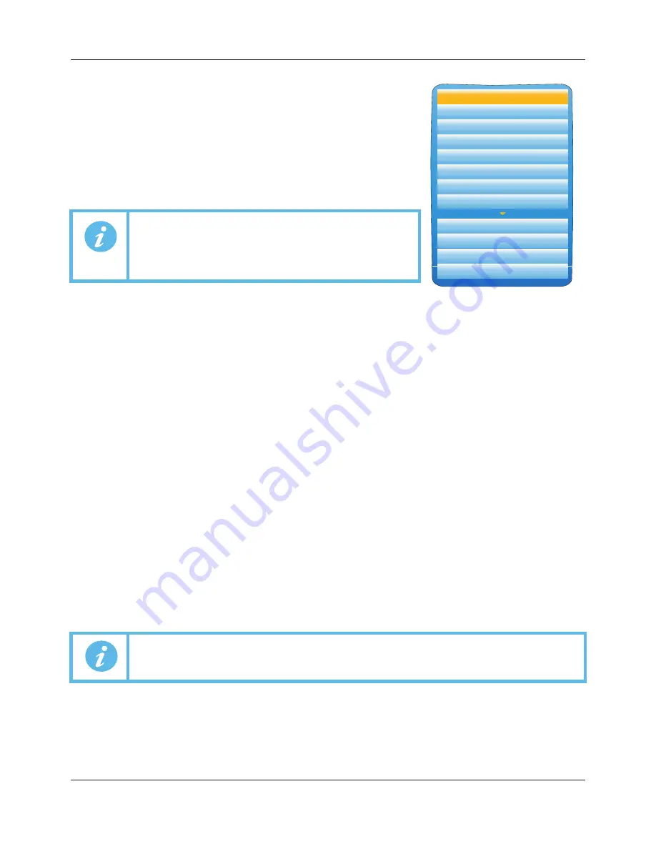
DISPLAY MODE SELECTION
Use the up/down arrow buttons to highlight the required display mode.
Once the required display mode is highlighted, operation of the scroll
button causes the recorder to leave the ‘Go to View’ menu and to display
channel values in the selected mode. See Section 5.4 for a description of
the various display modes.
Alternatively the up and down arrow buttons can be used from any of the
display modes to cycle through the available modes in the order listed in
the figure.
5.3.4 History
This top level menu item allows the user to switch from real-time trending to review mode, where channel val-
ues, messages, alarm triggers, etc. can be viewed back as far as the last significant configuration change. His-
tory mode is fully discussed in Section 5.5.
5.3.5 Faceplate Cycling on/off
For the purposes of this document the channel whose faceplate is currently displayed and whose ‘pen’ symbol
is visible is called the ‘Active’ channel.
By default, the recorder scrolls through all the channels in the display group, with each channel becoming the
active channel in turn. This top level menu ‘Faceplate Cycling’ item allows the user to inhibit this scrolling action
such that the currently active channel remains active permanently, or until a manual scroll is performed using
the scroll button (or until Faceplate Cycling is re-enabled).
‘Faceplate Cycling’ is highlighted by using the up/down arrow buttons. Once highlighted, the status can be
changed from ‘On’ to ‘Off’ or
vice-versa
using the scroll button. Operation of the ‘Page’ button returns to the
trend display.
5.3.6 Operator Notes
This area allows up to 10 notes to be created when logged in as Engineer, using either the text entry techniques
described in Section 5.6, or ‘iTOOLS’ described in Section 9. Once logged out, operating the scroll button whilst
a note is highlighted calls a selection box allowing the user either to send that note to the chart, or to write a
Custom Note.
CUSTOM NOTE
The Custom Note is written using the text entry techniques described in Section 5.6. Once the note is complete,
operation of the page button calls a confirmation display. The down arrow is used to highlight ‘Yes’, and when
the scroll key is then operated, the message is sent to the chart. The user name is added to the start of the
custom note when saved. This custom note is not retained for further use, so if it is required on a regular basis,
it is suggested that one of the Operator Notes 1 to 10 be configured (Engineer access level required) so that it
may be used instead.
5.3.7 Demand Archiving
This allows a user, with a high enough access level, to archive a selected portion of the recorder history, either
to a ‘memory stick’ plugged into the USB port at the rear of the recorder (Local Archiving), or to a PC, by means
of the FTP protocol (Remote Archiving). The archived data remains in the flash memory of the instrument. When
the flash memory is full, new data causes the oldest file(s) to be discarded.
The up and down arrow keys are used to navigate to the required field.
Note 1:
If an option is not fitted, its display mode is not
available for selection.
Note 2:
Some display modes must be enabled in Instrument.
Display configuration (Section 6.1.3) before they
become available.
Note:
Each note can contain up to 100 characters.
Alarm Summary
System Alarms
Message Summary
Vertical Trend
Horizontal Trend
Vertical Bargraph
Horizontal Bargraph
Numeric
Alarm Panel
Control
Modbus Master
EtherNet/IP
A5E45696052A Rev-AA


