FEC920: USER GUIDE
Page 37
A
September 18
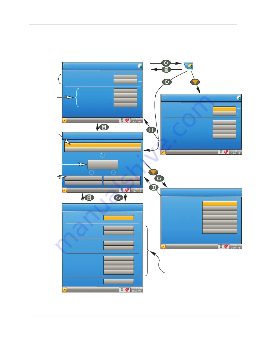
5.4.8 EtherNet/IP display mode
This display mode appears only if enabled in Instrument.Display configuration (Section 6.1.3) and is used to
display the input and output parameters assigned to the Client and Server input and output tables. Parameters
which have been configured with descriptors are identified by these descriptors instead of their ‘opc’ names
(shown in Figure 27).
Figure 27 Typical EtherNet/IP display
Virtual Channel.1.Main.In-
put1
EtherNet/IP Client
Loop.1.Setpoint.SP1
Loop.1.Setpoint.SP2
Loop.2.Setpoint.SP1
Loop.1.Setpoint.SP2
Inputs
Outputs
11.1
-19.1
123.0
132.0
246.2
Virtual Channel.1.Main.In-
put1
Loop.1.Setpoint.SP1
Loop.1.Setpoint.SP2
Loop.2.Setpoint.SP1
Loop.1.Setpoint.SP2
17.3
-12.9
123.0
132.0
246.2
111.11
123.123.123.223 : Point2Point :
1000ms
Server IP
address,
Connection type,
RPI
EtherNet/IP Client
123.123.123.222
Client (IO)
Explicit 1
No Connection
Explicit 2
No Connection
IP address and
mode of
operation for this
unit
IO Server Configuration
Mode Client (IO)
Input Instance
Size (Bytes)
100
100
Output Instance
Size (Bytes)
112
100
Server Address
Priority
RPI (ms)
Connection Type
123.123.123.223
Scheduled
1000
Point2Point
Reset No
These items appear only for the Client
The list of parameters can be scrolled
through using the up/down arrows.
Items with green arrows can be edited if the
user is logged in with the correct access level.
See
‘Explicit data’
below
IO Server Identity
Vendor Number
Device Type
Product Code
Revision
Status Word
Serial number
Product Name
45
0
E780
n.nn
0
8D01904C
Nano
Data depends on the slave.
EtherNet/IP Client
A5E45696052A Rev-AA


