Page 28
SITRANS LC500 – OPERATING INSTRUCTIONS
7ML19985GE04
Int
e
rc
onnect
ion
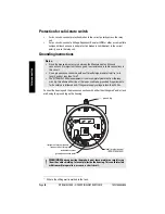
Connection Diagram
Recommended Cable Entries (equivalents can be
used)
General Purpose Cable Entry: M20 (A5E03252531) and ½" NPT
(A5E03252530)
1.
Strip cable and expose braided shield.
2.
Feed cable through dome nut and clamping insert. Fold braided shield over clamping
insert. Make sure that braided shield overlaps the O-ring by 3/32" (2 mm) and covers
the entry 360 degrees.
3.
Push clamping insert into body and tighten dome nut. Assemble into housing.
measuring signal
(mini-coaxial cable)
ground connection point
for instrument system
ground lug
instrument
system ground
4-20 mA current-
loop connection
(any polarity)
solid-state switch
relay (any polarity)
protective label
(see warning
above)
M20 x 1.5
6 mm (0.24")
24 mm
(0.94")
½" NPT
13 mm (0.51")
24 mm
(0.94")


