7ML19985GE04
SITRANS LC500 – OPERATING INSTRUCTIONS
Page 65
Appendix A
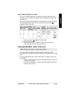
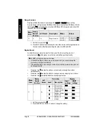
Lower Threshold Setting (2-state mode)
The Lower Threshold Setting is the % of range below which the probe is considered
uncovered. In order to switch the output signal, the corresponding delay time has to be
met (Menu 04).
The loop-current control (Menu 07) must be in 2-state mode for this menu to display the
Upper Threshold Setting in percent. As an extra identifier, a downward ramp
is
displayed to the right of the value.
1. Set the loop-current control (Menu 07) to 2-state mode.
2. Set the rotary switch to 6.
3. Press the RED (+) or BLUE (–) button to increase or decrease the value.
or: Press and hold a button to start a repeat function.
Analog Signalling Mode
(
2-state): menu level 0
The factory setting is for Analog mode (the loop-current is proportional with the
percentage of the range). When no buttons are pressed, the LCD displays the current mA
value.
2-state Signalling Mode provides a 4 mA or 20 mA output. The settings are relative to a
covered probe:
•
C: Hi selects a 20 mA signal for a covered probe, which switches to 4 mA if the
probe becomes uncovered.
•
C: Lo selects a 4 mA signal for a covered probe, which switches to 20 mA if the
probe becomes uncovered.
Menu
Item
Affected
by:
Rotary
Switch
Position
Left
Arrow
Mode
Added
Indicator
Description Values
06
07
6
Off
2-state
Downward
ramp at right
of value
Lower
Threshold
Setting
% of
range
Analog *
Display
shows
- - - -
Note:
Menu 08 has precedence over the settings in Menu 07.


