Page 68
SITRANS LC500 – OPERATING INSTRUCTIONS
7ML19985GE04
Appendix A
Digital Output Signalling (solid-state output): menu level 1
To set values for Upper and Lower Threshold Delay, and Upper and Lower Threshold
Setting, the solid-state switch output must be enabled (menu 17). When solid-state
switch output is disabled these menu selections display only - - - -.
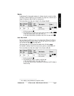
Upper Threshold Delay
(solid-state output)
The Upper Threshold Delay controls the Activation delay: the amount of time that has to
pass uninterrupted with the probe covered to a level above the Upper Threshold Setting
before the timer expires. After the timer expires, the output signal will comply to the
setting from Menu 18 for a covered probe. Whenever the level drops below the Upper
Threshold Setting before the timer expires, the timer is restarted.
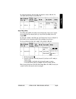
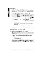
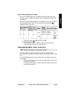
When the solid-state switch control (Menu 17) is disabled, menu 13 displays - - - -. When
the solid-state switch control is enabled, menu 13 displays the Activation delay in
seconds. As an extra identifier, an upward running d is displayed to the right of the value.
First select the solid-state switch output at menu 17 (contact open or contact closed).
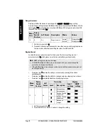
1. Set the rotary switch to 3.
2. Press the RED (+) or BLUE (–) button to increase or decrease the value.
or: Press and hold a button to start a repeat function.
or: Press both buttons simultaneously to toggle the value between minimum (0)
and maximum (100).
Menu
Item
Affected
by:
Rotary
Switch
Position
Left
Arrow
Mode
Identifier
Des-
cription
Values
13
17
3
On
Solid-state
switch con-
trol enabled
Upward
running d at
right of value
Upper
Threshold
Delay
Range: 0
to 100
(seconds)
Solid-state
switch con-
trol disabled
*
Display
shows
- - - -


