7ML19985GE04
SITRANS LC500 – OPERATING INSTRUCTIONS
Page 73
Appendix A
Miscellaneous
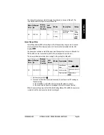
Output Signal Processing Test
Displays the Fault/Failure information. If operation is normal, two test displays alternate,
which light up all the LCD segments in a cycle. If there is a fault or failure, an error code is
displayed. See the detailed list of error codes and their meanings, page 53.
Set the rotary switch to 1.
To change the state of the output signals, press and hold both buttons simultaneously: the
digital mode outputs (the solid-state switch and the loop-current control in digital mode)
change to their opposite state. Thus 4mA becomes 20mA and contact open becomes
contact closed. This feature allows you to verify that the output signals are properly
processed further on in the PLC/DCS system: if the normal state is non-alarm, changing
the state should generate an alarm.
The outputs stay in the opposite state as long as both buttons are pressed.
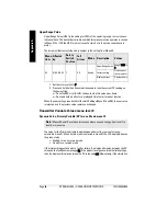
Factory Settings
Displays whether the factory settings are still in place, or how much they have been
changed, and allows you to restore the factory settings.
Set the rotary switch to 2. To restore the factory settings, press both buttons
simultaneously to change the LCD to ‘do it’ and hold both buttons for more than one
second. When the buttons are released, the LCD displays FAC A.
Menu
Item
Rotary
Switch
Position
Left Arrow
Description
11
1
On
Output Signal Processing Test
Menu
Item
Rotary
Switch
Position
Left Arrow
Description
LCD
Display
Meaning
12
2
On
Factory Settings
FAC A
No parameters
changed from factory
setting
FAC P
Range settings altered:
timers and thresholds
unchanged
FAC ?
More parameters have
been changed

