background image


Description 


3.3 Operation 

SITRANS P300 with HART communication 
Operating Instructions, 06/2005, A5E00359579-02 

3-3


Gauge pressure 

This version measures aggressive, non-aggressive and hazardous gases, vapors and 

liquids.  
The smallest measuring span is 8 mbar g, the largest 400 bar g. 

Level 

With appropriate parameter settings, the gauge pressure version measures the level of 

aggressive, non-aggressive and hazardous liquids.  
The level can be measured in an open container. 
The parts in contact with the measured medium are made of various materials, depending 

on corrosion resistance requirements. 

Absolute pressure 

This version measures the absolute pressure of aggressive, non-aggressive and hazardous 

gases, vapors and liquids.  
The smallest measuring span is 8 mbar a, the largest 30 bar a. 

3.3 

Operation 

Overview 

You can operate the basic settings of the pressure transmitter using the buttons on the 

device. The entire range of settings can be operated via HART communication. 

3.4 

Structure 

Overview 

The device comprises: 

• 

Electronics 

• 

Housing 

• 

Measuring cell 

Summary of Contents for SITRANS P300

Page 1: ...t Automation and Drives Process Instrumentation and Analytics 76181 KARLSRUHE GERMANY Transmitter SITRANS P300 with HART communication A5E00359579 02 www siemens com processinstrumentation 1PA5E00359579 A5E00359579 SITRANS P300 with HART communication Operating Instructions 06 2005 pressure measurement ...

Page 2: ......

Page 3: ...necting 5 Operation 6 Operating functions via HART 7 Commissioning 8 Specifications 9 Dimension drawings 10 Appendix A List of Abbreviations Acronyms B Pressure measurement technology Transmitter SITRANS P300 with HART communication Operating Instructions 06 2005 A5E00359579 02 ...

Page 4: ...re defined as persons who are authorized to commission ground and label devices systems and circuits in accordance with established safety practices and standards Prescribed Usage Note the following Warning This device may only be used for the applications described in the catalog or the technical description and only in connection with devices or components from other manufacturers which have bee...

Page 5: ...meplate 3 5 3 6 Mode of operation 3 5 3 6 1 Overview of mode of operation 3 5 3 6 2 Operation of the electronics 3 6 3 6 3 Measuring cell operation 3 7 4 Installation 4 1 4 1 Safety information for installation 4 1 4 2 Installing gauge and absolute pressure versions 4 3 4 2 1 Information for installing gauge and absolute pressure versions 4 3 4 2 2 Installation for gauge and absolute pressure 4 4 ...

Page 6: ...justing zero point 6 24 6 5 6 5 Blind adjusting limit point 6 25 6 5 7 Zero point calibration 6 25 6 5 8 Current sensor 6 26 6 5 9 Output current in case of fault 6 27 6 5 10 Locking keys 6 29 6 5 11 Releasing key or function lock 6 30 6 5 12 Characteristic curve 6 30 6 5 13 Inset point of the root extraction characteristic curve 6 31 6 5 14 Measured value display 6 32 6 5 15 Unit 6 33 7 Operating...

Page 7: ...er 7 29 7 21 5 Limit modules 7 30 7 21 5 1 Overview of limit modules 7 30 7 21 5 2 Monitoring of current saturation 7 30 7 22 Simulation 7 32 7 22 1 Overview of simulation 7 32 7 22 2 Simulation with a ramp function 7 33 7 22 3 Simulation as fixed value 7 33 7 23 Limit monitor 7 34 8 Commissioning 8 1 8 1 Safety instructions for commissioning 8 1 8 2 Instructions for commissioning 8 2 8 3 Introduc...

Page 8: ...nctions via keys 6 10 Table 6 5 Meaning of the lock modes 6 29 Table 6 6 Measurement type Device variables display 6 32 Table 6 7 Unit for pressure measured value display 6 33 Table 6 8 Unit for volumes measured value display 6 34 Table 6 9 Unit for mass measured value display 6 34 Table 6 10 Unit for level measured value display 6 34 Table 6 11 Unit for temperature measured value display 6 35 Tab...

Page 9: ...tem integration Installation path for PDM 03 2005 First edition FW 11 03 06 PDM V 6 00 Dev R 1 DD Rev 1 SITRANS P300 06 2005 02 FW 11 03 06 PDM V 6 00 Dev R 1 DD Rev 1 SITRANS P300 1 3 Further information Information The contents of these instructions shall not become part of or modify any prior or existing agreement commitment or relationship All commitments on the part of Siemens AG are containe...

Page 10: ...emens office You will find your local Siemens office on the Internet under www siemens de prozessinstrumentierung Click on Contact and select your closest town Product information on the Internet The operating instructions are a constituent part of the enclosed CD sitrans p TRANSMITTERS order number A5E00090345 and is available on the Internet at www siemens de sitransp Click on More Info and Oper...

Page 11: ...ified in these instructions Insofar as they are not expressly stated in these instructions all changes to the device are the sole responsibility of the user 2 3 Laws and directives The regulations of the test certification valid in your country are to be observed Electrical connection in hazardous zones with explosive atmospheres The national directives and laws for hazardous areas valid in your c...

Page 12: ...ing nA zone 2 Devices with non sparking protection may only be connected and disconnected when off circuit Warning Exposure to aggressive and hazardous media The device can be operated both at high pressure and with aggressive and hazardous media Therefore improper use of this device may lead to serious injury and or considerable damage to property Above all it must be noted when the device was in...

Page 13: ...ropriate qualifications for their activities Training or instruction authorization in operating and maintaining devices and systems according to the safety regulations for electrical circuits high pressures and aggressive as well as hazardous media For explosion proof devices Training or instruction authorization in carrying out work on electrical circuits for hazardous systems Training and instru...

Page 14: ...General safety instructions 2 5 Qualified Personnel SITRANS P300 with HART communication 2 4 Operating Instructions 06 2005 A5E00359579 02 ...

Page 15: ... a stand alone version supplied with the necessary auxiliary power as part of a complex system environment e g SIMATIC S7 System communication Communication is via the HART protocol using HART communicator with at least 4 MB available memory PC with HART modem on which appropriate software is available e g SIMATIC PDM Control system which is able to communicate via the HART protocol e g SIMATIC S7...

Page 16: ... independent direct current of 4 to 20 mA which is linearly proportional to the input pressure The pressure transmitter measures aggressive non aggressive and hazardous gases vapors and liquids It can be used for the following measurement types Gauge pressure Absolute pressure With appropriate parameter settings it can also be used for the following additional measurement types Level Volume Mass T...

Page 17: ...level can be measured in an open container The parts in contact with the measured medium are made of various materials depending on corrosion resistance requirements Absolute pressure This version measures the absolute pressure of aggressive non aggressive and hazardous gases vapors and liquids The smallest measuring span is 8 mbar a the largest 30 bar a 3 3 Operation Overview You can operate the ...

Page 18: ...l cable compartment the buttons for operation of the device and depending on the version the digital display are located under this cover The connections for the auxiliary power UH and the shield are in the cable compartment The cable gland is on the side of the housing The measuring cell with the process connection 5 is located on the underside of the housing Depending on the version of the devic...

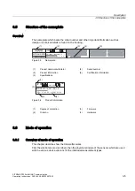
Page 19: ...75 16 3 0DGH LQ UDQFH 1U 0 Figure 3 3 Nameplate 1 Product name manufacturer 4 Serial number 2 Product information 5 Certification information 3 Specifications 3 6 3 3 0 Figure 3 4 Product information 1 Degree of protection 3 Firmware 2 Order no 4 Hardware 3 6 Mode of operation 3 6 1 Overview of mode of operation This chapter describes how the transmitter works First the electronics are described t...

Page 20: ...by the measuring amplifier 2 and digitized in an analog to digital converter 3 The digital signal is analyzed in a microcontroller 4 and corrected with regard to linearity and thermal characteristics It is then converted in a digital to analog converter 5 into the output current of 4 to 20 mA A diode circuit provides reverse voltage protection You can make an uninterrupted current measurement with...

Page 21: ...erview The following modes of operation are described Gauge pressure Absolute pressure The following process connections are available for example G 14 NPT Front flush membrane F B and pharma flange Bioconnect Biocontrol Caution If the measurement signal fails because of sensor breakage the seal diaphragm may also be destroyed In the worst case the process medium escapes at the process connection ...

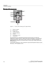
Page 22: ...ge pressure sensor pe Input pressure The input pressure pe is transferred to the gauge pressure sensor 6 via the seal diaphragm 4 and the fill liquid 5 displacing its measuring diaphragm The displacement changes the resistance value of the four piezo resistors in the measuring diaphragm in a bridge circuit The change in the resistance causes a bridge output voltage proportional to the input pressu...

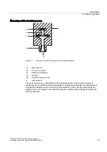
Page 23: ...s connection 3 Separating diaphragm 4 Fill liquid 5 Absolute pressure sensor pe Input pressure The input pressure pe is transferred to the absolute pressure sensor 6 via the seal diaphragm 3 and the fill liquid 4 displacing its measuring diaphragm The displacement changes the resistance value of the four piezo resistors in the measuring diaphragm in a bridge circuit The change in the resistance ca...

Page 24: ...5 Fill liquid 6 Gauge pressure sensor pe Input pressure The input pressure pe is transferred to the gauge pressure sensor 6 via the seal diaphragm 4 and the fill liquid 5 displacing its measuring diaphragm The displacement changes the resistance value of the four piezo resistors in the measuring diaphragm in a bridge circuit The change in the resistance causes a bridge output voltage proportional ...

Page 25: ...ell 2 Process connection 3 Separating diaphragm 4 Fill liquid 5 Absolute pressure sensor pe Input pressure The input pressure pe is transferred to the absolute pressure sensor 6 via the seal diaphragm 3 and the fill liquid 4 displacing its measuring diaphragm The displacement changes the resistance value of the four piezo resistors in the measuring diaphragm in a bridge circuit The change in the r...

Page 26: ...Description 3 6 Mode of operation SITRANS P300 with HART communication 3 12 Operating Instructions 06 2005 A5E00359579 02 ...

Page 27: ... selected materials for the wetted parts are suitable for the process media used Ignoring this safety measure may cause bodily and life threatening injury and damage the environment Caution Contact protection is required for surface temperatures 70 C The shock protection must be designed in such a way that if there is a buildup of heat the maximum permitted ambient temperature at the device is not...

Page 28: ...tion certificate The operator may use the device under non atmospheric conditions outside the limits specified in the EC type examination certificate or the certification applicable in the country of use at the operator s own risk if safety measures which may be necessary in accordance with use conditions explosive mixture have been taken The limit values specified in the general specifications ar...

Page 29: ...ithin the permitted ambient temperature values Note Protect the transmitter against Direct heat radiation Rapid temperature fluctuations Heavy contamination Mechanical damage Notice Compare the desired operating data with the data on the nameplate Notice The housing may only be opened for maintenance local operation or to make electrical connections Installation configuration The transmitter may i...

Page 30: ...ll the transmitter below the pressure tapping point Lay the pressure tubing with a constant gradient to the pressure tapping point so that any gas pockets can escape in the main line See also Introduction to commissioning Page 8 2 4 2 2 Installation for gauge and absolute pressure Notice When installing the process connection of the pressure transmitter do not turn it on the housing Procedure To i...

Page 31: ...e as possible to the measuring point Vibration free Within the permitted ambient temperature values Note Protect the transmitter against Direct heat radiation Rapid temperature fluctuations Heavy contamination Mechanical damage Notice Compare the desired operating data with the data on the nameplate Notice The housing may only be opened for maintenance local operation or to make electrical connect...

Page 32: ...be adjusted ME Limit point ΔpME Limit point to be adjusted p Pressure ρ Density of the measured medium in the container hU Zero point g Local gravitational acceleration hO Limit point Note Select the height of the container flange for recording of the transmitter measuring point such that the lowest level to be measured is always over the flange or at its upper edge 4 3 2 Installation for level No...

Page 33: ...ansmitter for level proceed as follows 1 Attach the seal to the container s mating flange Ensure that the seal is centrically positioned and that it does not restrict the movement of the flange s seal diaphragm in any way as otherwise the tightness of the process connection is not guaranteed 2 Screw on the transmitter s flange 3 Observe the installation position ...

Page 34: ...Installation 4 3 Installation for level version SITRANS P300 with HART communication 4 8 Operating Instructions 06 2005 A5E00359579 02 ...

Page 35: ... cable diameter of 7 to 12 mm for the IP65 or IP68 protection rating Warning Observe the provisions of the test certification valid for your country When making electrical connections observe the national statutes and provisions for hazardous areas valid for your countries In Germany these are for example Operational safety regulations Directive for the installation of electrical systems in hazard...

Page 36: ...ding to HART Connect a load of at least 230 ohms into the signal circuit in sequence in order to guarantee fault free HART communication When using supply isolation for SMART transmitters for example Siemens 7NG4021 a load is already installed in the device 5 2 Connecting the transmitter Requirement ದ Figure 5 1 Connecting 1 Supply terminals 3 Auxiliary power UH 2A Shield support with plastic cabl...

Page 37: ...ert the cable set via the cable gland through a guide channel The guide channel connects the cable gland with the cable compartment 4 Connect the strands to the supply terminals 1 and Observe the polarity when doing this 5 If you have a stainless steel cable gland place the shield on the cable gland 2B If you have a plastic steel cable gland place the shield on the shield support 2A The shield sup...

Page 38: ...Connecting 5 2 Connecting the transmitter SITRANS P300 with HART communication 5 4 Operating Instructions 06 2005 A5E00359579 02 ...

Page 39: ... on site and via HART communication first the local operation and then the operating functions via HART will be described If there are references to further information on an aspect described here these will always be found at the end of a chapter under See also Overview Contents Safety information for operation Information on operation Digital display Local operation Overview of operating functio...

Page 40: ...otection yes yes except for overriding write protection Unit yes yes User specific characteristic no yes Diagnostics function no yes Measurement type no yes Further operating functions are accessible via HART for special applications If the device does not have a digital display you can only operate a limited selection on the device However the selection of functions available via HART is not affe...

Page 41: ...ess allows for a rough adjustment over a wide range For fine adjustment use the UP or DOWN button again Press the button again Violations of the measured value limits are displayed on the digital display with or To operate the device via the keyboard the button lock must be released If you operate the transmitter locally write access via HART is not possible during this time However it is possible...

Page 42: ... local display of the measured value 1 with Unit 2 Mode 4 Symbol 6 Status 5 and 7 The measured value 1 display displays the following depending on the customer setting The current emitted by the transmitter The percentage measurement value of the adjusted measurement type e g level realtive to the adjusted measurement range The measurement value in a physical unit which can be selected The display...

Page 43: ...hed off Display Figure 6 2 Examples for current and bar graph measured value display The following messages may appear as a ticker in the bottom line of the digital display They have no influence on the current output Table 6 2 Message as ticker Ticker Meaning DIAGNOSTIC WARNING Is always displayed if An event configured by the user is to be signaled with a warning e g Limit reached Event counter ...

Page 44: ...Display Figure 6 3 Example of error message The following messages may appear as a ticker in the bottom line of the digital display Ticker Meaning HARDWARE FIRMWARE ALARM Contains hardware faults such as incorrect checksum incorrect EEPROM data defective EEPROM RAM fault ROM fault inconsistent data EEPROMs not initialized DIAGNOSTIC ALARM Is always displayed if an event configured by the user is t...

Page 45: ...t meaning depending on the mode setting The table below shows the meanings of the arrows in the respective functions Meaning Table 6 3 Meaning of the arrow displays Function Mode Display Display Adjusting zero point 2 exceeds of the upper current limit exceeds of the lower current limit Adjusting limit point 3 exceeds of the upper current limit exceeds of the lower current limit Adjusting damping ...

Page 46: ...t 6 4 6 Overflow range Description The output signal is divided into defined ranges Measuring range Saturation limits Fault current The transmitter emits the output current according to the device variables selected as primary variable PV The operating range of the current lies between 4 mA and 20 mA Meaning When the measurement limits are exceeded or not reached the measured values are correctly ...

Page 47: ... signal See also Fault current Page 7 18 Setting the current limits Page 7 19 6 5 Local operation 6 5 1 Local control elements Introduction The transmitter can be operated on site with the keys buttons Selectable modes can be used to choose and execute the functions described in the table The number of functions is limited if the device does not have a digital display Control elements Figure 6 5 P...

Page 48: ... Electrical damping 4 Damping higher Damping lower Set to 0 Time constant T63 in seconds Adjustment range 0 0 s to 100 0 s Zero point in so called blind adjustment 5 Pressure higher Pressure lower Setting zero point to 0 Zero point in the selected pressure unit Limit point in so called blind adjustment 6 Pressure higher Pressure lower Setting limit point to upper measuring limit Limit point in the...

Page 49: ...de you have presumably not selected lin in mode 11 Select lin Measured value display 13 Select from three options Display type input value Output current in mA Measured value in Unit 14 Select from the table for measured values display In each case the first value from the table of the physical unit Physical unit See also Operating functions via HART communication Page 7 1 Overview of operation Pa...

Page 50: ...fied ammeters appropriate for the transmitter Specific test certificates If the transmitter is used as category 1 2 equipment observe the EC type examination certificate or the certification valid for you country Note The housing should be cleaned to prevent dirt and moisture entering the device To operate the device via the keys the key lock must be released Procedure The device is set to measure...

Page 51: ...s If the transmitter is not using the Pressure measurement type this mode is skipped in local operation Difference The difference between setting and adjusting lies in the calculation Setting with reference pressure Requirement Two reference pressures pr1 and pr2 are available The reference pressures are initialized by the process or generated by a pressure sensor With setting a desired zero point...

Page 52: ...HW DFWXDO DFWXDO WDUJHW Explanations for the example of setting with reference pressure A The measuring range is from 0 to 16 bar You are changing the zero point from 0 to 2 bar and the limit point from 16 to 14 bar The span is then 12 bar B 2 bar process pressure is created Use the MODE key to switch the transmitter to mode 2 To set the zero point press the keys UP and DOWN simultaneously for 2 s...

Page 53: ... current value with the aid of a reference pressure This function is particularly suitable when the required pressures for zero point and limit point are not available After adjustment the span specified on the nameplate may no longer correspond with the setting Using the formulae below the current to be set for the desired zero point and limit point can be calculated To calculate the output curre...

Page 54: ... calculation formula for adjusting with reference pressure can be used to calculate the current to be adjusted for the desired zero point IMA 13 mA at 2 bar with the existing reference pressure It can be adjusted with the keys UP or DOWN IMA C Use the MODE key to set the transmitter to mode 3 The Current calculation formula for adjusting can be used to calculate the current to be adjusted for the ...

Page 55: ...nt to 4 mA proceed as follows 1 Create the reference pressure 2 Set mode 2 3 Set the zero point to 4 mA 4 Save with the Mode key Adjusting zero point If you do not set the output current but continually adjust it you must mathematically calculate the currents to be adjusted To adjust the output current of the zero point proceed as follows 1 Create the reference pressure 2 Set mode 2 3 Adjust the o...

Page 56: ...3 Setting adjusting limit point Introduction The zero point for the pressure transmitter can be set or adjusted in mode 3 Both the zero point and limit point can be adjusted separately or both values successively Requirement You are familiar with the correct operation of the transmitter and the associated safety information You have selected a reference pressure which corresponds to the limit poin...

Page 57: ...justing limit point without digital display You have a device with a cover without an inspection window and do not want to set the limit point but rather adjust it An ammeter is required to do this To adjust the output current of the limit point proceed as follows 1 Connect the ammeter to the test connector 2 Create the reference pressure 3 Press and hold down the MODE key 4 Adjust the output curr...

Page 58: ...Set mode 4 2 Press the keys UP and DOWN simultaneously 3 Save with the MODE key Result Electrical damping is set to 0 seconds Adjusting requirement The basic calibration of the steps is a 0 1 second interval The longer you depress the UP and DOWN key the greater the steps Adjusting electrical damping To adjust the electrical damping proceed as follows 1 Set mode 4 2 Adjust the desired damping 3 Sa...

Page 59: ...m in the device These theoretical pressure values are allocated to the standard current values 4 mA and 20 mA Depending on the model and measuring range a maximum downscaling of 1 100 can be achieved span ratio r turn down The correlation between the measured pressure and the output current generated is linear Example of adjusting blind A Initial situation B Blind adjusting zero point C Blind adju...

Page 60: ...ent the resulting current cannot be set above these limits With a marked elevation of the zero point the limit point must therefore previously be reduced such that it still lies within the permitted range after elevation of the zero point Setting without reference pressure Blind setting resets the zero point to the lower sensor limit and the limit point to the upper sensor limit Note If the preset...

Page 61: ...ted a pressure unit Procedure To blind set the zero point proceed as follows 1 Set mode 5 2 Press the keys UP and DOWN simultaneously for 2 seconds See also Operating via keys Page 6 12 6 5 6 3 Blind setting the limit point Introduction Blind setting resets the limit point to the upper sensor limit Note Changes to modes 5 and 6 effect the pressure scaling only The scaling for level or user specifi...

Page 62: ...d 6 effect the pressure scaling only The scaling for level or user specific characteristic curve remains unaffected by it Therefore only pressure measured values and pressure units are displayed in these modes It is possible to switch between a rising and falling characteristic curve Requirement You are familiar with the correct operation of the transmitter and the associated safety information Th...

Page 63: ...es by interchanging the values for zero and limit points Requirement You are familiar with the correct operation of the transmitter and the associated safety information There is no reference pressure and you have selected a pressure unit Procedure To blind adjust the pressure value of the limit point proceed as follows 1 Set mode 6 2 Adjust the pressure value of the limit point 3 Save with the MO...

Page 64: ... absolute pressure transmitter Note You need a reference pressure known to you which lies within the measuring limits To calibrate the zero point proceed as follows 1 Create the reference pressure 2 Set mode 7 3 Set the reference pressure on the digital display 4 Save with the MODE key See also Operating via keys Page 6 12 6 5 8 Current sensor Introduction The pressure transmitter is set to consta...

Page 65: ...current operation proceed as follows Press MODE in mode 8 See also Operating via keys Page 6 12 6 5 9 Output current in case of fault Introduction When a fault occurs the lower fault current is displayed in the basic setting In mode 9 you can choose between the output of the upper and lower fault current The standard values 36 mA and 22 8 mA are set The standard values of the upper and lower fault...

Page 66: ... fault current To reset the fault current to the basic setting proceed as follows Press the keys UP and DOWN simultaneously Fault causes Fault currents may be triggered by FW alarm HW alarm Diagnostic interrupt Sensor breakage Measured value status BAD Reference NAMUR recommendation NE43 of Jan 18 1994 Standardization of the signal level for the breakdown information of digital transmitters with a...

Page 67: ...tter are locked Exception Releasing key lock The device can be operated by means of HART communication LO Keys on the transmitter are partially locked Exception Setting zero point Releasing key lock The device can be operated by means of HART communication LS Keys on the transmitter are partially locked Exception Setting zero point Setting limit point Releasing key lock The device can be operated ...

Page 68: ... for 5 seconds Remove write protection To release a write protection for HART L using the keys proceed as follows Press MODE for 5 seconds See also Operating via keys Page 6 12 Monitoring of current saturation Page 7 30 6 5 12 Characteristic curve Introduction The characteristic curve representing the relationship between the output current and input pressure can be adjusted in mode 11 Set lin wit...

Page 69: ... root extraction characteristic curve Introduction If you have reached mode 12 you have already set a root extraction characteristic curve in mode 11 A root extraction characteristic curve is only meaningful for a differential pressure transmitter Requirement You are familiar with the correct operation of the transmitter and the associated safety information Procedure To deactivate mode 12 proceed...

Page 70: ...sure P 1 Sensor temperature t SE 2 Electronics temperature t EL 3 Pressure value untrimmed P UNC 4 Level LEVEL 5 Volume Vol 6 Mass MASS 7 Volume of flow not relevant for gauge and absolute pressure V Flo 8 Mass flow rate not relevant for gauge and absolute pressure M Flo 9 User CUSt Requirement You are familiar with the correct operation of the transmitter and the associated safety information Pro...

Page 71: ...on You have already selected the desired measured value display in mode 13 Procedure To adjust the physical unit proceed as follows 1 Set mode 14 2 Select a unit 3 Save with the Mode key Units Table 6 7 Unit for pressure measured value display Unit Display mbar mbar bar bar mm water gauge 4 C 39 F m4H2O Inch water gauge 4 C 39 F i4H2O ATM ATM Torr TORR g cm2 Gcm2 Kg cm2 KGcm2 MPa MPa KPa KPa Pa Pa...

Page 72: ... gallons Gal British gallons imGal British barrels bbl British barrels liquid bblli Bushels buShl Yard3 Yd3 Foot3 FT3 Inch3 in3 Standard l STdl Standard m3 STdm3 Standard feet3 STFT3 Table 6 9 Unit for mass measured value display Unit Display Gram G Kilogram KG Tons T Short tons STon Long tons lTon Pounds lb Ounces OZ Table 6 10 Unit for level measured value display Unit Display Foot FT Inch inch ...

Page 73: ... communication Operating Instructions 06 2005 A5E00359579 02 6 35 Table 6 11 Unit for temperature measured value display Unit Display Celsius C Fahrenheit F Kelvin K Rankine R See also Operating via keys Page 6 12 Selection of the physical unit Page 7 22 ...

Page 74: ...Operation 6 5 Local operation SITRANS P300 with HART communication 6 36 Operating Instructions 06 2005 A5E00359579 02 ...

Page 75: ...ftware is described in separate operating instructions or in the online help for both these tools As soon as you have set up the HART communication and the transmitter you can adapt the transmitter to your relevant measuring task by setting a few parameters When doing so you are assisted by the measurement types Pressure Level and a user programmable Characteristic curve One or more device variabl...

Page 76: ...characters 7 3 Measurement When the communication indicator is flashing on the digital display the pressure transmitter is exchanging data via HART communication 7 4 Selecting the measurement type 7 4 1 Measurement type selector Measurement type selector The device variables Pressure Sensor temperature Electronics temperature and Pressure untrimmed are active regardless of the measurement type and...

Page 77: ...ed using the buttons in the following order Pressure Sensor temperature Electronics temperature Pressure untrimmed When operating via HART communication you will find the following as well Measurement type selector You can use this selector to switch between the measurement types Pressure Level and a characteristic curve that can be programmed by the user The device variables are always active and...

Page 78: ...n define these limit values within the individual block functions The dynamic variables Primary Secondary Tertiary and Quarternary PV SV TV QV can be interconnected with any active device variables Various different measurement type examples are conceivable with a 4 bar pressure transmitter See also Measured value status Page 7 10 7 4 4 Measurement type Pressure Introduction The Pressure measureme...

Page 79: ...y Variable ME Limit value SV Secondary Variable TV Tertiary Variable QV Quarternary Variable 7 4 5 Customized characteristic curve Introduction The customized characteristic curve is continuously active as an identical function in the two following measurement types Level and User This means that it always provides a result for the following function thus also influencing the measured value status...

Page 80: ...se The pairs of values 0 0 and 100 100 are set as default values In principle rising and falling characteristics can be configured However with regard to the device variable status rising characteristics are preferable since otherwise HIGH LIMIT and LOW LIMIT will have the opposite meaning See also Measured value status Page 7 10 7 4 6 Measurement type Level Introduction Once you have configured t...

Page 81: ...he following functions in all three blocks in the same way Ideally this range corresponds to the sensor limits of the transmitter that are assumed in a calculation example for all blocks with 0 and 4 bar However you can also set a downscaling of e g 1 2 This means that 50 of the nominal measuring range i e 2 bar in this example controls fully 100 of the following characteristic curve Use the Outpu...

Page 82: ...from 0 and 100 l a volume of 50 l is yielded for process pressure of 1 bar The Level parameter setting also still automatically activates the device variable for the mass If you have not yet configured a value for the density the initial value of 1 kg l is preset With a value of 5 kg l a mass value of 250 kg is yielded in the example for the device variable Mass Note When the density changes the m...

Page 83: ...YLFH YDULDEOHV 3UHVVXUH 6HQVRU WHPSHUDWXUH OHFWU FRPS WHPSHUDWXUH 3UHVVXUH XQWULPPHG HYHO 9ROXPH 0DVV 8VHU 0DSSHU QDPLF YDULDEOHV VHOHFWLRQ QDORJ RXWSXW VFDOLQJ 0 0 XQLW Figure 7 4 Measurement type User DV Device Variable MA Zero value PV Primary Variable ME Limit value SV Secondary Variable TV Tertiary Variable QV Quarternary Variable The first function Input scaling pressure defines here too the...

Page 84: ...output block With a zero point of 0 vessels and a limit point of 1000 vessels a value of 250 vessels is yielded in the example for the User device variable at a process pressure of 0 5 See also Measured value status Page 7 10 Analog output block Page 7 13 7 4 8 Measured value status Introduction Every device variable is assigned a status byte to indicate the quality of the measured values This sta...

Page 85: ...iable Pressure has the status BAD Since the measurement type selector is set to USER the device variable User is also given the status BAD The reasons for changes to the status of a device variable are summarized in the table If there were several reasons for a change in status MANUAL always has the highest priority BAD follows as next highest and UNCERTAIN as the third highest priority 49 79 69 3...

Page 86: ...l converter in overrange under range DV3 more than 20 outside the sensor limits DV2 MANUAL Analog to digital converter in overrange Analog to digital converter in underrange 4 Level If DV0 BAD When DV0 is simulated DV0 UNCERTAIN DV not active DV0 HIGH LIMIT DV0 LOW LIMIT 5 Volume DV0 BAD Characteristic curve is faulty When DV0 is simulated DV0 UNCERTAIN Input value is outside the specified charact...

Page 87: ...curve is run 7 4 9 Analog output block Introduction The analog output block converts the value provided by the dynamic Primary Variable PV into a current value of 4 to 20 mA When you actuate the measurement type selector you automatically define the zero point and limit point to the current values 4 and 20 mA respectively By default the limit values of the corresponding device variables as entered...

Page 88: ...HUDWXUH 3UHVVXUH XQWULPPHG 0 P 0 P HYHO 9ROXPH 0DVV 8VHU 0DSSHU QDPLF YDULDEOHV VHOHFWLRQ QDORJ RXWSXW VFDOLQJ 0 0 XQLW Figure 7 7 Analog output scaling DV Device Variable MA Zero value PV Primary Variable ME Limit value SV Secondary Variable TV Tertiary Variable QV Quarternary Variable Description of measurement type Level 3ULPDU YDULDEOH S EDU VURII VUOLQ VUOLQ OLQHDU 39 OHYHO P QSXW VFDOLQJ 0 0...

Page 89: ...ctor the Primary Variable PV and the display unit defined with the PV you can scale the value shown on the digital display as desired and allocate it any unit of 5 characters To do so use the Digital Display Settings item in SIMATIC PDM or in the HART Communicator This scaling is based on the percentage value of the PV which is also used for scaling the current output In other words set the output...

Page 90: ...QWV WHPSHUDWXUH 3UHVVXUH XQWULPPHG HYHO 9ROXPH 0DVV 8VHU 0DSSHU QDPLF YDULDEOHV VHOHFWLRQ QDORJ RXWSXW VFDOLQJ 0 P 0 P Figure 7 9 Free LCD scaling DV Device Variable MA Zero value PV Primary Variable ME Limit value SV Secondary Variable TV Tertiary Variable QV Quarternary Variable 7 5 Setting zero point and limit point You can set the zero point and the limit point using the SIMATIC PDM or HART Co...

Page 91: ...from the installation position Procedure Pressurize the device Pressure Level or evacuate it Absolute pressure 0 1 of the measuring span Perform the zero point calibration using SIMATIC PDM or the HART Communicator If you do not have a vacuum perform a trimming of the lower sensor trim point for a known reference pressure Caution For absolute pressure transmitters the zero point is at vacuum A zer...

Page 92: ...or the measured value For this reason good accuracy can only be achieved by setting the measuring span to the maximum 7 10 Current sensor Description The transmitter can be switched to constant current operation for test purposes In that case the current no longer corresponds to the process variable A C appears in the mode display of the digital display 7 11 Fault current Description You can use t...

Page 93: ...eset limits of the current output signal The specified accuracy of the current output signal is only valid within the current limits 4 to 20 mA S P 0HDVXULQJ UDQJH Figure 7 10 Current limits 1 Linear control range 2 Lower saturation limit default value 3 Upper saturation limit default value 4 Lower fault current value default value 5 Upper fault current value default value 6 Recommended setting ra...

Page 94: ...be operated by means of the keys and HART communication LA Keys on the transmitter are locked Exception Releasing key lock The device can be operated by means of HART communication LO Keys on the transmitter are partially locked Exception Setting zero point Releasing key lock The device can be operated by means of HART communication LS Keys on the transmitter are partially locked Exception Setting...

Page 95: ...figure the displayed pressure unit with an add on GAUGE G or ABS A The add on has no effect on the real measured value To do so select the option Gauge or Absolute under the Pressure display type menu command There are two options for the display If the pressure unit is 5 characters an A or a G is added at the end respectively If the pressure unit is 5 characters the letters GAUGE or ABS flash alt...

Page 96: ...n You can use this to switch on the Bar graph function in the device display so that it alternates with the unit display When the device is delivered the Bar graph function is switched off See also Elements of the digital display Page 6 4 7 17 Sensor trim 7 17 1 Sensor trim Description The sensor trim can be used to set the characteristic curve of the transmitter at two sensor trim points The resu...

Page 97: ...n by performing a lower sensor trim at 100 mbar Note The accuracy of the test device should be three times as high as that of the transmitter 7 17 2 Trimming of the sensor trim point Trimming the lower sensor trim point The pressure at which the lower sensor trim is to be performed is applied at the transmitter Via SIMATIC PDM or the HART Communicator you instruct the transmitter to accept this pr...

Page 98: ...r compensating inaccuracies in the processing chain following the transmitter Example of an application The current is to be measured as a voltage drop from 1 to 5 V at a resistance of 250 Ohm 5 To trim the tolerance of the resistance set the current sensor so that the voltage drop at 4 mA is exactly 1 V and at 20 mA is exactly 5 V 1 Trim at 4 mA Use the current sensor trim menu option to instruct...

Page 99: ...not affected by this Note If a multimeter is used it must always be sufficiently accurate P P 3DUDOOHO RIIVHW KDQJH LQ JUDGLHQW 0HDVXUHG FXUUHQW 1RPLQDO FXUUHQW Figure 7 13 Current sensor trim A Output curve B Characteristic curve after current sensor trim 4 mA C Characteristic curve after current sensor trim 20 mA 7 19 Factory calibration Introduction You can use factory calibration to reset the ...

Page 100: ...urrent 5 Variable mapper This performs the following setting PV Pressure SV Sensor temp TV Electronics temp QV Non linearized pressure PV Primary Variable SV Secondary Variable TV Tertiary Variable QV Quarternary Variable 7 20 Static configuration data Description A further menu command in the corresponding operating program allows you to read and also write a series of sensor specific material da...

Page 101: ...e values Limit monitoring of all device variables The diagnostics strategy employed for SITRANS P300 incorporates a diagnostic warning and a diagnostic interrupt for diagnostic functions for monitoring limit values e g for monitoring current saturation This warning and interrupt can be configured Diagnostic warning The device transmits via HART communication the diagnostic event that has occurred ...

Page 102: ...er the first time period has elapsed a calibration or service warning will be issued After a second time period which can be configured as a time differential a diagnostic interrupt is reported and fault current is output To perform calibration work you need to acknowledge warnings and interrupts You can then reset the timers and switch off the monitoring function The calibration intervals for the...

Page 103: ... the timer and deactivates it 7 21 4 Min max pointer Description The transmitter provides three min max pointer pairs which you can use to monitor the three measured variables Pressure Sensor temperature and Electronics temperature for negative and positive peak values For each measured value a resettable min max pointer saves the maximum and minimum peak values in long term storage in the two non...

Page 104: ...tware such as SIMATIC PDM You need to configure two time periods The first time period specifies how long the current output is allowed to be in saturation response time before an interrupt is triggered and the device outputs its set fault current The second time period stop time specifies the duration of the interrupt In the first example the response time starts at time t1 when the current reach...

Page 105: ...DXOW FXUUHQW 5HVSRQVH WLPH 5HVSRQVH WLPH 5HVSRQVH WLPH RZHU IDXOW FXUUHQW DPSOH DPSOH DPSOH 6WRS WLPH 6WRS WLPH 7LPH V Figure 7 15 Saturation monitoring with saturated interrupt value S SPD SPLQ P V 0LQ 0LQ W W W W W W W W 5HVSRQVH WLPH 5HVSRQVH WLPH 5HVSRQVH WLPH DXOW FXUUHQW DPSOH DPSOH DPSOH 6WRS WLPH 6WRS WLPH 7LPH Figure 7 16 Saturation monitoring with active interrupt value at top ...

Page 106: ...ostic function you can receive and process quasi measurement data onsite or in the control room without having process pressure or a temperature value This allows you to run individual process sequences in the cold state and thus simulate process states In addition if you inject simulation values you can test the line routing from the control room to the individual transmitter The value to be simu...

Page 107: ...th a rising or falling tendency can move The step width can be calculated with the step number which is also adjustable You can specify the rate of rise of the ramp via the duration of the individual ramp steps QFUHPHQW 8SSHU UDQJH YDOXH ಥ RZHU UDQJH YDOXH 1XPEHU RI VWHSV 7 22 3 Simulation as fixed value Description Taking the physical unit into account you can set a fixed simulation value for all...

Page 108: ...the measurement type selected Limit monitoring warning interrupt Select whether a warning or a warning plus an interrupt should be triggered when a limit is violated Limit monitoring upper lower Specify here whether a device variable monitors the upper limit the lower limit or both limits Upper limit value Upper limit value in the unit of the device variable Lower limit value Lower limit value in ...

Page 109: ... warning plus an interrupt should be triggered Limit monitoring warning interrupt upper limit Select whether a warning or a warning plus an interrupt should be triggered when the event counter upper limit is violated Limit monitoring warning interrupt lower limit Select whether a warning or a warning plus an interrupt should be triggered when the event counter lower limit is violated Reset event c...

Page 110: ...nitor SITRANS P300 with HART communication 7 36 Operating Instructions 06 2005 A5E00359579 02 Messages from the limit monitor and from the event counter can be acknowledged separately Resetting the event counter starts a new monitoring interval ...

Page 111: ... EC type examination certificate or the certification valid in your country Warning Intrinsically safe If a non conforming supply unit is used the intrinsically safe protection type will no longer be effective and the approval certification will be invalid Warning Fixed installation Devices to be operated in hazardous areas should be connected with fixed cable installation This is not necessary wi...

Page 112: ... Note The operating data have to correspond to the values on the nameplate When you switch the auxiliary power on the transmitter is in operation 8 3 Introduction to commissioning Following commissioning the transmitter is immediately ready for use To obtain stable measured values the transmitter needs to be allowed to warm up for five minutes or so after the power supply is switched on The measur...

Page 113: ...r bleed screw 3 Pressure line 4 Shut off valve 5 Drain valve 6 Compensation vessel steam only Requirement All valves are closed Procedure To commission the transmitter for steam or liquid proceed as follows 1 Open the shut off valve for the test connection 2B 2 Via the test connection of the shut off module 2 apply the pressure corresponding to the zero point to the pressure transmitter 1 3 Check ...

Page 114: ...ions 06 2005 A5E00359579 02 6 Open the shut off valve 4 at the pressure tapping point 7 Open the shut off valve to the process 2A 8 5 Commissioning for gases Overview Usual arrangement Special arrangement Measuring gases above the pressure tapping point Measuring gases below the pressure tapping point ...

Page 115: ...al 7 Drain valve Requirement All valves are closed Procedure To commission the transmitter for gases proceed as follows 1 Open the shut off valve for the test connection 2B 2 Via the test connection of the shut off module 2 apply the pressure corresponding to the zero point to the pressure transmitter 1 3 Check the zero point 4 If the zero point differs from the value desired correct it 5 Close th...

Page 116: ...Commissioning 8 5 Commissioning for gases SITRANS P300 with HART communication 8 6 Operating Instructions 06 2005 A5E00359579 02 ...

Page 117: ...802 psi g 400 bar g 5802 psi g Lower measuring limit Measuring cell with silicone oil 30 mbar a 0 44 psi a Measuring cell with inert liquid For process temperature ϑ 20 C ϑ 60 C 4 F ϑ 140 F 30 mbar a 0 44 psi a For process temperature ϑ 60 C ϑ 100 C 140 F ϑ 212 F 30 mbar a 20 mbar a ϑ 60 C C 0 44 psi a 0 29 psi a ϑ 108 F F Upper measuring limit Measuring cell with silicone oil 100 of maximum measu...

Page 118: ...th 0 1 s Set to 0 1 s 0 100 s Current sensor 3 55 mA 23 mA Failure signal 3 55 mA 23 mA Load Resistor R Ω 8 9 P 5 Without HART communication UH Auxiliary power With HART communication HART Communicator R 230 500 Ω SIMATIC PDM R 230 1100 Ω Characteristic curve Linearly rising or linearly falling Measuring accuracy Reference conditions Rising characteristic curve Zero point 0 bar Seal diaphragm stai...

Page 119: ... with silicone oil 40 C 85 C 40 F 185 F Measuring cell with inert liquid 20 C 85 C 4 F 185 F Digital display 30 C 85 C 22 F 185 F Storage temperature 50 C 85 C 58 F 185 F Climatic class Condensation permitted Degree of protection As per EN 60 529 IP65 IP68 NEMA 4X enclosure cleaning resistant to lyes steam to 150 C Electromagnetic compatibility Spurious emission and resistance to interference As p...

Page 120: ...nsmitter DC 10 5 V 42 V In the case of intrinsically safe operation DC 10 5 V 30 V Ripple USS 0 2 V 47 125 Hz Noise Ueff 1 2 V 0 5 10 Hz Certificates and approvals Classification according to Pressure Equipment Directive PED 97 23 EC For gases of Fluid Group 1 and liquids of Fluid Group 1 meets requirements of Article 3 Para 3 Good engineering practice Water waste water In preparation Explosion pr...

Page 121: ...29 psi g 0 01 1 bar g 0 15 14 5 psi g 4 bar g 58 psi g 0 04 4 bar g 0 58 58 psi g 7 bar g 102 psi g 0 16 16 bar g 2 3 232 psi g 21 bar g 305 psi g 0 6 63 bar g 9 1 914 psi g Depending on the process connection the measuring span may differ from these values 67 bar g 972 psi g Lower measuring limit Measuring cell with silicone oil 30 mbar a 0 44 psi a Upper measuring limit Measuring cell with silic...

Page 122: ...ment deviation with cut off point setting including hysteresis and repeatability Linear characteristic curve r 10 0 0029 r 0 071 10 r 30 0 0045 r 0 071 30 r 100 0 005 r 0 05 Settling time T63 without electrical damping Approx 0 2 s Long term drift at 30 C 54 F In 5 years 0 25 r Influence of ambient temperature As percentage at 10 60 C 14 140 F 0 1 r 0 2 at 40 10 C and 60 85 C 40 14 F and 140 185 F...

Page 123: ...y Spurious emission and resistance to interference As per EN 61 326 and NAMUR NE 21 Process conditions Medium temperature Measuring cell with silicone oil 25 C 150 C 13 F 302 F 25 C 200 C 13 F 392 F with temperature decoupler Design Weight Approx 1 13 kg 2 2 29 lb Material Wetted parts materials Process connection Stainless steel mat no 1 4404 316L Seal diaphragm Stainless steel mat no 1 4404 316L...

Page 124: ... waste water In preparation Explosion protection Intrinsic safety i PTB 05 ATEX 2048 Identification Ex II 1 2 G EEx ia ib IIB IIC T4 T5 T6 Permissible ambient temperature 40 85 C 40 185 F temperature class T4 40 70 C 40 158 F temperature class T5 40 60 C 40 140 F temperature class T6 Connection To certified intrinsically safe circuits with maximum values Ui 30 V Ii 100 mA Pi 750 mW Ri 300 Ω Effect...

Page 125: ...300 with HART communication Operating Instructions 06 2005 A5E00359579 02 10 1 Dimension drawings 10 10 1 SITRANS P300 gauge pressure absolute pressure FD FD FD FD ෘ FD Figure 10 1 SITRANS P300 with oval flange ...

Page 126: ... gauge pressure absolute pressure flush mounted r ෘ FD FD Figure 10 2 SITRANS P300 flush mounted The diagram shows a SITRANS P300 with an example of a flange In this drawing the height is subdivided into H1 and H2 H1 Height of the SITRANS P300 up to a defined cross section H2 Height of the flange up to this defined cross section Height H2 only is indicated in the dimensions of the flanges ...

Page 127: ...5 mm 2 2 50 16 165 mm 6 5 Approx 55 mm 2 2 50 40 165 mm 6 5 Approx 55 mm 2 2 80 16 200 mm 7 9 Approx 55 mm 2 2 80 40 200 mm 7 9 Approx 55 mm 2 2 Flanges as per ASME ASME B 16 5 DN CLASS D H2 1 150 110 mm 4 3 Approx 53 mm 2 1 1 300 125 mm 4 9 Approx 53 mm 2 1 1 1 2 150 130 mm 5 1 Approx 53 mm 2 1 1 1 2 300 155 mm 6 1 Approx 53 mm 2 1 2 150 150 mm 5 9 Approx 53 mm 2 1 2 300 165 mm 6 5 Approx 53 mm 2...

Page 128: ...ox 55 mm 2 2 80 40 127 mm 5 Approx 55 mm 2 2 DIN 11864 1 DN PN D H2 25 40 52 4 mm 2 1 Approx 54 mm 2 1 40 40 65 4 mm 2 6 Approx 54 mm 2 1 50 40 78 4 mm 3 1 Approx 54 mm 2 1 100 40 130 6 mm 5 1 Approx 54 mm 2 1 DIN 11864 2 DN PN D H2 25 40 70 mm 2 8 Approx 49 mm 1 9 40 40 82 mm 3 2 Approx 49 mm 1 9 50 40 94 mm 3 7 Approx 49 mm 1 9 100 40 159 mm 6 3 Approx 49 mm 1 9 DIN 11864 3 DN PN D H2 25 40 50 5...

Page 129: ...mm 3 6 Approx 53 mm 2 1 80 40 106 mm 4 2 Approx 53 mm 2 1 100 40 119 mm 4 7 Approx 53 mm 2 1 Other connections Varivent connector DN PN D H2 25 32 40 66 mm 2 6 Approx 53 mm 2 1 40 125 40 84 mm 3 3 Approx 53 mm 2 1 10 5 Bioconnect Biocontrol BioconnectTM connector BioconnectTM screw connector DN PN D H2 25 40 55 mm 2 2 Approx 57 mm 2 2 50 40 82 mm 3 2 Approx 57 mm 2 2 100 40 145 mm 5 7 Approx 57 mm...

Page 130: ...m 1 9 80 40 106 mm 4 2 Approx 48 mm 1 9 100 40 119 mm 4 7 Approx 48 mm 1 9 Other connections BiocontrolTM connector DN PN D H2 25 40 64 mm 2 5 Approx 48 mm 1 9 50 40 90 mm 3 5 Approx 48 mm 1 9 100 40 120 mm 4 7 Approx 48 mm 1 9 Connect STM flanged joint DN PN D H2 25 40 85 mm 3 3 Approx 47 mm 1 9 32 40 95 mm 3 7 Approx 47 mm 1 9 40 40 100 mm 3 9 Approx 47 mm 1 9 50 40 110 mm 4 3 Approx 47 mm 1 9 6...

Page 131: ...ART communication Operating Instructions 06 2005 A5E00359579 02 10 7 10 6 PMC Style Connections for the paper industry PMC Style Standard DN PN D H2 40 4 mm 1 6 Approx 36 8 mm 1 4 M44x1 25 cap nut PMC Style Minibolt DN PN D H2 26 3 mm 1 Approx 33 1 mm 1 3 ...

Page 132: ...Dimension drawings 10 6 PMC Style SITRANS P300 with HART communication 10 8 Operating Instructions 06 2005 A5E00359579 02 ...

Page 133: ...S P300 with HART communication Operating Instructions 06 2005 A5E00359579 02 A 1 Appendix A A 1 Overview of HART operating structure The following overview applies to the HART communicator operating structure ...

Page 134: ...atus 2 Temperature Values 1 Sens Temp 2 Sens Temp status 3 Electr Temp 4 Electr Temp status 3 Level Vol Mass Values 1 Level shown if valid items 2 Level status 3 Volume 4 Volume status 5 Mass 6 Mass status 4 Vol Mass Flow 1 Vol Flow shown if valid items 2 Vol Flow status 3 Mass Flow 4 Mass Flow status 5 Appl Stat 1 Customer shown if valid items 2 Customer Status 3 Quick Setup 1 Tag 2 Ext TAG M 3 P...

Page 135: ...es unit 2 Untrimmed Pres USL 3 Untrimmed Pres LSL 4 Untr Pres min span additional if measurement 5 Level 1 Level unit is mapped to level 2 Level USL 3 Level LSL 4 Level min span additional if measurement 6 Volume 1 Volume unit is mapped to level 2 Volume USL 3 Volume LSL 4 Volume min span additional if measurement 7 Mass 1 Mass unit is mapped to level 2 Mass USL 3 Mass LSL 4 Mass min span addition...

Page 136: ...facturer 2 Sensor trim 1 Sensor trim points 1 Lower sensor trim point 2 Upper sensor trim point 2 Sensor trim 1 Pres zero trim M 2 Lower sensor trim M 3 Upper sensor trim M 3 Trimpoint summary 3 Trim analog output 1 D A trim M 2 Scaled D A trim M 4 Position correction 1 Position corr M 3 Simulation Test 1 Loop test M Simulation AO 2 Inputs M Simulation Fixed Ramp 4 Access Control 1 Local keys cont...

Page 137: ...A 2 Certifications The certifications are enclosed as a loose collection of operating instructions or on CD A 3 Pressure equipment directive The monitoring of the design dimensioning testing and manufacture to ensure it is in accordance with Module H comprehensive quality assurance by TÜV North as the appointed body ...

Page 138: ...onformity rating Pressure equipment of categories I to IV must comply with the safety requirements of the directive and be assigned the CE symbol They must comply with a conformity rating procedure according to Appendix III of the directive Pressure equipment according to Article 3 Paragraph 3 must be designed and manufactured in agreement with the sound engi neering practice SEP applying in a mem...

Page 139: ...cond dash Exception fire extinguishers and bottles for breathing appara tus at least Category III Liquids of fluid group 1 Vessels according to Article 3 Number 1 1 Letter b First dash Liquids of fluid group 2 Vessels according to Article 3 Number 1 1 Letter b Second dash Exception modules for producing warm water Fuelled pressure equipment or equipment heated in another manner above 110 C and lia...

Page 140: ...ories I and II must be included in Category III Gases of fluid group 2 Pipelines according to Article 3 Number 1 3 Letter a Second dash Exception liquids at temperatures 350 C belonging to Cat egory II must be included in Category III Liquids of fluid group 1 Pipelines according to Article 3 Number 1 3 Letter b First dash Liquids of fluid group 2 Pipelines according to Article 3 Number 1 3 Letter ...

Page 141: ... bar a bar absolute Unit of pressure for absolute pressure bar g bar gauge Unit of pressure for gauge pressure lb Pound Unit of weight psi a psi absolute Unit of pressure for absolute pressure psi g psi gauge Unit of pressure for gauge pressure Table B 3 Other abbreviations Abbreviation In full Meaning PED Pressure equipment directive HART Highway Addressable Remote Transducer Standard protocol fo...

Page 142: ...List of Abbreviations Acronyms B 1 Pressure transmitter abbreviations SITRANS P300 with HART communication B 2 Operating Instructions 06 2005 A5E00359579 02 ...

Page 143: ...tibility 9 3 9 7 EMC 9 3 9 7 F Firmware 3 5 Flange 4 6 H HART Modem 3 1 L LCD 3 4 LCD scaling 7 14 Load 9 6 With HART communication 9 2 Without HART communication 9 2 M Mapper 7 4 Measured value display 6 30 Measurement 7 2 Measurement type selector 7 2 Message OVER 6 8 UNDER 6 8 N Nameplate 3 5 O Operating structure A 1 Order no 3 5 P PED A 5 Position correction 6 25 Pressure equipment directive ...

Page 144: ...Index SITRANS P300 with HART communication Index 2 Operating Instructions 06 2005 A5E00359579 02 Z Zero point calibration 6 25 ...

Page 145: ......

Page 146: ...t Automation and Drives Process Instrumentation and Analytics 76181 KARLSRUHE GERMANY Transmitter SITRANS P300 with HART communication A5E00359579 02 www siemens com processinstrumentation 1PA5E00359579 A5E00359579 SITRANS P300 with HART communication Operating Instructions 06 2005 pressure measurement ...

Reviews: