7ML19985JS01
SITRANS RD200 – OPERATING INSTRUCTIONS
Page 13
m
mmmm
Connect
io
ns
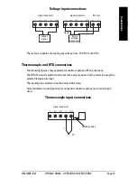
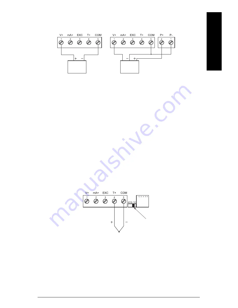
The meter is capable of accepting any voltage from -10 V DC to +10 V DC.
Thermocouple and RTD connections
The following figures show examples for thermocouple and RTD connections.
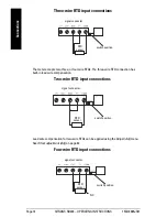
The RTD/TC selector switch must be set to the proper position for the meter to accept the
selected temperature input.
The input type is selected using the Setup (
SEtu
) menu.
Selected thermocouple input must correspond to thermocouple sensor and wire type
used.
voltage
signal
3-wire
voltage
transducer
signal connector
signal connector
signal
24 V out
Thermocouple input connections
signal connector
TC
switch position
Voltage input connections
Summary of Contents for SITRANS RD200
Page 1: ...SITRANS Communications and Displays SITRANS RD200 Operating Instructions 11 2012 ...
Page 12: ...Page 8 SITRANS RD200 OPERATING INSTRUCTIONS 7ML19985JS01 mmmmm Dimensions Notes ...
Page 56: ...Page 52 SITRANS RD200 OPERATING INSTRUCTIONS 7ML19985JS01 mmmmm Advanced Features Notes ...
Page 62: ...Page 58 SITRANS RD200 OPERATING INSTRUCTIONS 7ML19985JS01 mmmmm Troubleshooting Notes ...
Page 88: ...Page 84 SITRANS RD200 OPERATING INSTRUCTIONS 7ML19985JS01 mmmmm Serial Communication Notes ...
Page 102: ...Page 98 SITRANS RD200 OPERATING INSTRUCTIONS 7ML19985JS01 mmmmm Modbus Register Notes ...
Page 105: ......


