background image

Page 72

SITRANS RD200 – OPERATING INSTRUCTIONS

7ML19985JS01

mmm

mm

S

e

rial Co

mmun

icat

io

n

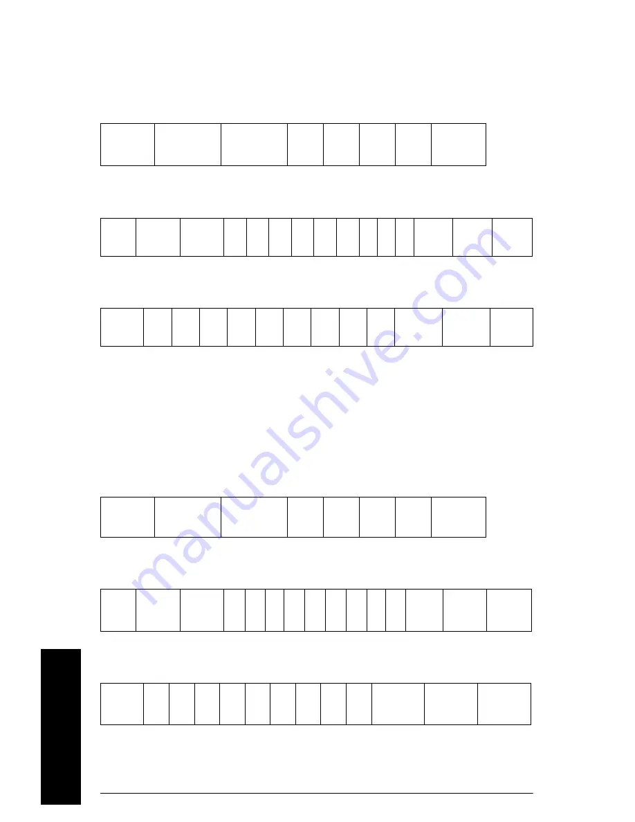
Command: Read

Command: Write

Reply: Write and Read

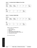
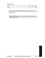
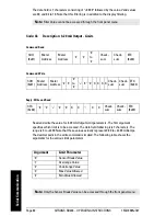
The data field is 7 characters consisting of “+000” followed by the value. The range is 002 
to 999. Note that these values actually represent 0.2 to 99.9. The decimal point is implied.

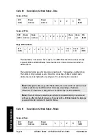
Command: Read

Command: Write

Reply: Write and Read

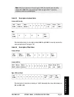
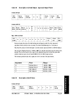
Code: 23

Description: Bypass Value

SOH
(0x01)

Meter 
Address

Meter 
Address

‘2’

‘3’

‘9’

‘B’

ETX
(0x03)

SOH
(0x01)

Meter 
Address

Meter 
Address

‘2’ ‘3’ ‘+’ ‘0’ ‘0’ ‘0’ X X X

Check-
sum

Check-
sum

ETX
(0x03)

STX
(0x02)

‘2’

‘3’

‘+’

‘0’

‘0’

‘0’

X

X

X

Check-
sum

Check-
sum

ETX
(0x03)

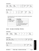
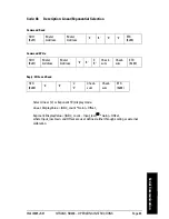
Code: 24

Description: Adjustment Value

SOH
(0x01)

Meter 
Address

Meter 
Address

‘2’

‘4’

‘9’

‘A’

ETX
(0x03)

SOH
(0x01)

Meter 
Address

Meter 
Address

‘2’ ‘4’

‘+’
‘-‘

‘0’ ‘0’ ‘0’ X X X

Check-
sum

Check-
sum

ETX
(0x03)

STX
(0x02)

‘2’

‘4’

‘+’
‘-‘

‘0’

‘0’

‘0’

X

X

X

Check-
sum

Check-
sum

ETX
(0x03)

Summary of Contents for SITRANS RD200

Page 1: ...SITRANS Communications and Displays SITRANS RD200 Operating Instructions 11 2012 ...

Page 2: ...und version and in electronic version We encourage users to purchase authorized bound manuals or to view electronic versions as designed and authored by Siemens Milltronics Process Instruments Siemens Milltronics Process Instruments will not be responsible for the contents of partial or whole reproductions of either bound or electronic versions While we have verified the contents of this manual fo...

Page 3: ...nections 12 Serial Communication 15 Relays and 24 V Output Connections 15 4 to 20 mA Output and Input Signal Connections 15 Setup 17 Front panel buttons and status LED indicators 17 Display functions and messages 18 Main menu 20 Setting numeric values 20 Setting up the meter SEtu 20 Setting the input signal inPt 21 Setting the decimal point dEc P 23 Setting the temperature scale F C 23 Setting rel...

Page 4: ...copy function CoPY 47 Internal calibration ICAL 48 Troubleshooting 50 Operation 53 Front panel buttons operation 53 Maximum Minimum readings 53 Appendix A Factory Defaults 55 Appendix B Troubleshooting Tips 57 Appendix C Quick User Interface Reference Guide 59 Appendix D Serial Communication Protocol PDC 61 SITRANS RD200 PDC 61 Table of Commands 62 Command Packet Format 63 Reply Packet Format 64 R...

Page 5: ...communication options make SITRANS RD200 an excellent addition to any system Safety Notes Special attention must be paid to warnings and notes highlighted from the rest of the text by grey boxes CAUTION relates to the caution symbol on the product and means that failure to observe the necessary precautions can result in electric shock WARNING relates to a caution symbol on the product and means th...

Page 6: ...provides information on the following Product specifications Outline diagrams Installation requirements Wiring diagrams How to program the unit Principles of operation Troubleshooting tips Factory defaults Quick user reference If you have any questions comments or suggestions about the manual contents please email us at techpubs smpi siemens com For the complete library of Siemens Milltronics manu...

Page 7: ...onal Single power supply one 24 V DC 10 200 mA maximum Dual power supplies one 24 V DC 10 200 mA maximum and one 24 V DC 10 40 mA maximum External loop power supply 35 V DC maximum Input impedance Voltage ranges greater than 1 MΩ Current ranges 50 100 Ω depending on resettable fuse impedance Output loop resistance 24 V DC 10 to 700 Ω maximum 35 V DC external 100 to 1200 Ω maximum Mounting Location...

Page 8: ...to 9999 automatic lead zero blanking Eight intensity levels 2x option 30 5 mm 1 20 high red LED Update Rate Process RTD 3 7 to 5 second Thermocouple 1 8 to 2 5 second Overange Display flashes 9999 Underange Display flashes 1999 Outputs mA Analog 4 to 20 mA Isolated optional Relays1 2 SPDT Form C relays 3A optional Auto initializing All relays rated 3A 30 V DC or 3A 250 V AC non inductive 1 All rel...

Page 9: ...ector Setup Meter address PDC protocol 0 to 99 Modbus protocol 1 to 247 Baud rate 300 to 19200 bps Transmit time delay Programmable between 0 and 199 ms or transmitter always on for RS 422 communication Data 8 bit 1 start bit 1 stop bit Parity None even or odd Modbus only PDC protocol does not use parity Byte to Byte timeout 0 01 to 2 54 sec Modbus only Turn around delay Less than 2 ms fixed Refer...

Page 10: ... Type T 0 1 Res 1 C in range 180 0 to 371 C 1 8 F in range 199 9 to 700 F RTD temperature 100 Ω RTD 1 C in range 200 to 750 C 1 F in range 328 to 1382 F Enclosure High impact plastic UL 94V 0 Color gray Degree of protection front panel Type 4X NEMA 4X IP65 panel gasket provided 62 mm x 119 mm x 106 mm 2 45 x 4 68 x 4 19 H x W x D Optional thermoplastic stainless steel steel for 1 6 meters all with...

Page 11: ...ONS Page 7 mmmmm Dimensions Dimensions RD200 Meter Dimensions Side View RD200 Case Dimensions Top View 45 mm 1 76 62 mm 2 45 15 mm 0 59 81 mm 3 2 91 mm 3 6 Screw terminal connector 0 5 Nm 4 5 lb in tightening torque 64 mm 2 5 119 mm 4 68 92 mm 3 61 ...

Page 12: ...Page 8 SITRANS RD200 OPERATING INSTRUCTIONS 7ML19985JS01 mmmmm Dimensions Notes ...

Page 13: ...ckets provided with the meter Back off the two screws so that there is 6 4 mm or less through the bracket Slide the bracket toward the front of the case and remove 3 Insert meter into the panel cutout 4 Install mounting brackets and tighten the screws against the panel To achieve a proper seal tighten the mounting bracket screws evenly until meter is snug to the panel along its short side DO NOT O...

Page 14: ...nstallation Panel Cutout and Mounting 92 mm 3 622 square corners to 1 5 mm 0 060 max radius A 45 mm 1 772 panel cutout to DIN 43700 B tolerances A 0 8 mm 0 032 0 0 mm 0 000 B 0 6 mm 0 024 0 0 mm 0 000 mounting bracket mounting screw removable connectors panel gasket ...

Page 15: ...larity connection The and symbols are only a suggested wiring convention Notes Verify that all system components are installed in accordance with instructions All connections are made to removable screw terminal connectors located at the rear of the meter WARNING Use copper wire with 60 C or 60 75 C 140 F or 140 167 F insulation for all line voltage connections Observe all safety regulations Elect...

Page 16: ...rmed through the front panel buttons The current input is protected against current overload by a fuse capable of being reset The display may or may not show a fault condition depending on the nature of the overload The fuse limits the current to a safe level when it detects a fault condition and automatically resets itself when the fault condition is removed Transmitter powered by ext supply or s...

Page 17: ...ctions The RTD TC selector switch must be set to the proper position for the meter to accept the selected temperature input The input type is selected using the Setup SEtu menu Selected thermocouple input must correspond to thermocouple sensor and wire type used voltage signal 3 wire voltage transducer signal connector signal connector signal 24 V out Thermocouple input connections signal connecto...

Page 18: ...d wire compensation Lead wire compensation for two wire RTDs can be applied using the Adjust Adj menu See Offset adjustment Adj on page 42 Three wire RTD input connections switch position signal connector RTD sensor Two wire RTD input connections signal connector switch position RTD sensor Four wire RTD input connections signal connector switch position RTD sensor NC ...

Page 19: ...ctor labeled RELAY1 RELAY2 on Connector Labeling for Two Relays and 24 V Supply on page 11 The COM common terminals of the relays should not be confused with the COM common terminal of the SIGNAL connector The 24 V DC output is available at the connector labeled 24V OUT next to the relay connector 4 to 20 mA Output and Input Signal Connections Connections for the 4 to 20 mA transmitter output are ...

Page 20: ... mmmmm Connections 4 to 20 mA Output and Input Signal Powered by Meter signal connector 2 wire 4 to 20 mA transmitter remote display chart recorder mA out 24 V out 4 to 20 mA Output Powered Externally remote display chart recorder mA out external power supply ...

Page 21: ... front panel buttons After power and signal connections have been completed and verified apply power to the meter See Appendix C Quick User Interface Reference Guide on page 59 for more details Front panel buttons and status LED indicators Notes The meter is factory calibrated prior to shipment for all input types in milliamps volts and degrees respectively The calibration equipment is certified t...

Page 22: ... 4 20 mA Set meter for 4 to 20 mA input 0 10 0 10 VDC Set meter for 10 VDC input rtd RTD Set meter for RTD input A385 Alpha 385 Set α 0 00385 European curve 100Ω RTD A392 Alpha 392 Set α 0 00392 American curve 100Ω RTD tC TC Set meter for TC input 0 J 0 J Type J 1 k 1 K Type K 2 T 2 T Type T 3 t 0 3 T 0 Type T 0 1 resolution 4 E 4 E Type E F C F or C Set temperature scale F F Set meter to Fahrenhe...

Page 23: ...time delay dLy2 Delay2 Enter relay 2 time delay setup On2 On2 Set relay 2 on time delay OFF2 Off2 Set relay 2 off time delay Aout Analog Output Enter the Analog Output menu SEbr Sensor break Program TC or RTD sensor break value for analog out out1 Output 1 Program output 1 value e g 4 mA out2 Output 2 Program output 2 value e g 20 mA ProG Program Enter the Program menu ScAL Scale Enter the Scale m...

Page 24: ...ck The display moves to the next menu every time a setting is accepted by pressing Enter Ack Setting numeric values The numeric values are set using the Right and Up arrow buttons When in programming mode and setting a numeric value press Right arrow to select next digit and Up arrow to increment digit value The digit being changed is displayed brighter than the rest Press Enter Ack at any time to...

Page 25: ...g Mode SEtu is displayed 2 Press Enter Ack to access Setup menu inPt is displayed 3 Press Enter Ack to access Input menu 4 Press Up arrow to scroll through choices 4 20 0 10 tC rtd 5 When 4 20 is displayed press Enter Ack to accept this choice 6 Press Menu to return to Run Mode Setup meter to display voltage 0 10 input 1 Press Menu to enter Program Mode 2 Press Enter Ack to access Setup menu 3 Pre...

Page 26: ...Program Mode SEtu is displayed 2 Press Enter Ack to access Setup menu inPt is displayed 3 Press Enter Ack to access Input menu 4 Press Up arrow to scroll through choices 4 20 0 10 tC rtd 5 When rtd is displayed press Enter Ack 6 The display shows A385 or A392 Select the coefficient to match the RTD sensor either 0 00385 European curve or 0 00392 American curve Press Enter Ack to accept your select...

Page 27: ...ft to right 6 Press Enter Ack to accept the displayed setting 7 Press Menu to return to Run Mode Setting the temperature scale F C Set meter to display temperature in degrees Fahrenheit or Celsius 1 Press Menu to enter Program Mode SEtu is displayed 2 Press Enter Ack to access Setup menu 3 Press Up arrow until temperature selection menu is displayed F C 4 Press Enter Ack to access the temperature ...

Page 28: ...0 199 seconds Off delay 0 199 seconds Set Up Relays rLY1 rLY2 Set points SEt1 SEt2 and Reset points rSt1 rSt2 1 Press Menu to enter Program Mode 2 SEtu is displayed Press Enter Ack to access the Setup menu 3 Press Up arrow until rELy is displayed 4 Press Enter Ack to enter Relay menu 5 rLy1 is displayed Press Enter Ack to set up relay 1 6 Act1 is displayed The relay Action menu allows the user to ...

Page 29: ...urn to Run Mode Setting fail safe operation FLSF FLS1 FLS2 The fail safe operation is set independently for each relay Select on to enable or select off to disable fail safe operation Set up relays for fail safe operation 1 Press Menu to enter Program Mode 2 Press Enter Ack to access the Setup menu 3 Press Up arrow until rELy is displayed 4 Press Enter Ack to enter Relay menu 5 Press Up arrow unti...

Page 30: ...Press Menu to enter Program Mode 2 Press Enter Ack to access the Setup menu 3 Press Up arrow until rELy is displayed 4 Press Enter Ack to enter Relay menu 5 Press Up arrow until dLAy is displayed 6 Press Enter Ack to enter Time Delay Menu dLy1 is displayed 7 Press Enter Ack to set time delay for relay 1 On1 is displayed 8 Press Enter Ack to proceed 9 Press Up arrow to change digit and Right arrow ...

Page 31: ...t Reset For Manual reset mode Enter Ack can be pressed at any time to turn off relay For relay to turn back on signal must go below setpoint and then go above it Input Set Reset Relay LED Relay LED ACK pressed Relay LED Relay LED Manual latching Automatic or Manual non latching Automatic non latching energized on de energized off Manual only after passing below Reset latching with clear ACK presse...

Page 32: ...y time to turn off relay For relay to turn back on signal must go above setpoint and then go below it Input Set Reset Relay LED Relay LED ACK pressed Relay LED Relay LED Manual latching Automatic or Manual non latching Automatic non latching energized on de energized off Manual only after passing above Reset latching with clear ACK pressed ACK pressed ...

Page 33: ...when the time delay has elapsed If the signal drops below the set point high alarm before the time delay has elapsed the On time delay timer resets and the relay does not change state The same principle applies to the OFF time delay The LED is not affected by Time Delay when Automatic or Manual reset mode is selected Rather the LED follows the set and reset points Input Set Reset Relay LED On Time...

Page 34: ...gized in non alarm condition In case of a power failure the relay will go to alarm state Input Set Reset Relay LED Relay LED ACK pressed Relay LED Relay LED Manual latching Automatic or Manual non latching Automatic non latching energized on de energized off Manual only after passing below Reset latching with clear ACK pressed ACK pressed ...

Page 35: ...ized in non alarm condition In case of a power failure the relay will go to alarm state Input Set Reset Relay LED Relay LED ACK pressed Relay LED Relay LED Manual latching Automatic or Manual non latching Automatic non latching energized on de energized off Manual only after passing above Reset latching with clear ACK pressed ACK pressed ...

Page 36: ...hing Input LEDs indicate the relay status Relay 2 Set Relay 1 Set Relay 1 and 2 Reset Pump 1 Pump 2 Relay 2 Set Relay 1 Set Relay 1 Reset Pump 1 Pump 2 Relay 2 Reset Relay 2 Set Relay 1 Set Relay 2 Reset Pump 1 Pump 2 Relay 1 Reset Input Input de energized energized de energized energized de energized energized ...

Page 37: ... 3 Press Up arrow until the Aout menu is displayed Press Ent Ack to accept scal is displayed 4 Press Ent Ack to access the scale menu diS1 is displayed 5 Press Enter Ack to set value for display 1 6 Press Up arrow to change digit and Right arrow to change active digit 7 Press Enter Ack to accept setting out1 is displayed 8 Press Enter Ack to set value for output 1 9 Press Up arrow to change digit ...

Page 38: ... arrow and Menu for three seconds to access Advanced Features menu of the meter 2 Press Up arrow until the SELc menu is displayed Press Ent Ack to accept 3 Press Up arrow until the out menu is displayed Press Ent Ack to accept 4 Press Up arrow until the Aout menu is displayed Press Ent Ack to accept 5 Press Ent Ack to access the scale menu 6 Press Up arrow until sEbr is displayed Press Ent Ack to ...

Page 39: ...e the meter simply program the inputs and corresponding display values Scale the meter without a signal source 1 Press Menu to enter Program Mode 2 Press Up arrow until ProG appears in the display 3 Press Enter Ack to access Programming functions ScAL is displayed 4 Press Enter Ack inP1 is displayed 5 Press Enter Ack to access scale adjustment for input 1 6 Press Up arrow to change the digit and t...

Page 40: ... and input 2 signals required to complete the calibration or scaling of the meter Calibrating the SITRANS RD200 CAL Recalibration is recommended at least every twelve months The meter can be calibrated to display the process in engineering units by applying the appropriate input signal and following the calibration procedure The use of a calibrated signal source is strongly recommended to calibrat...

Page 41: ...t scale this will give a greater degree of accuracy to the calibration The scale can be changed to the Celsius scale after calibration is completed The meter will display temperature accurately in any scale The following table shows the recommended low and high calibration points for all types 1 Connect signal to the meter using the appropriate wire for example type J thermocouple wire to recalibr...

Page 42: ...e J and program display 2 accordingly See Recommended Calibration Points on page 37 After the meter accepts input 2 the display flashes the message CJr that indicates the meter is sensing the cold junction reference This completes the recalibration procedure for the selected input Recalibrating process inputs ICAL The Internal Calibration ICAL menu located in the Advanced features menu is used to ...

Page 43: ...on page 20 6 Press Enter Ack to accept password settings Program settings are now protected against unauthorized changes Record the password for future reference If appropriate it may be recorded in the space provided Unlocking the meter unLC If the meter is password protected the correct password must be entered in order to change parameters Entering the correct four digit number sets the passwor...

Page 44: ...n Mode To try again press Enter Ack while the Locked message LoCd is displayed Forgot the Password The password may be disabled by the following procedure 1 Note the display reading prior to pressing the Menu button 2 Ignore decimal point and sign 3 Access the Password menu add 2 to the noted reading and enter that number as the password for example display reading 1 23 password 0125 ...

Page 45: ...SErL Serial Set serial communication parameters Prot Protocol Enter the Protocol menu PdC PDC Select PDC protocol mbs Modbus Select Modbus protocol Addr Address Set meter address bAud Baud rate Select baud rate trdE Transmit delay Set transmit delay for serial communication prty Parity Select none even or odd Modbus only tbyt Byte to byte Program byte to byte timeout silent time Modbus only CoPy C...

Page 46: ...nctions or excessive lead wire resistance in RTDs The offset adjustment value is automatically reset to zero whenever the type of temperature sensor is changed i e Thermocouple type or RTD curve ICAL Initial calibration Enter initial calibration Available for process inputs only Curr Current Calibrating current input I Lo I low Calibrate low current input I Hi I high Calibrate high current input v...

Page 47: ...Up arrow to scroll through the Advanced Features Menu options When the Filter menu FLtr is displayed press Ent Ack to access the menu 3 Press Up arrow to change the active digit and press Right arrow to advance to the next digit 4 Press Ent Ack to accept display setting 5 Press Menu to exit at any time Noise filter bypass bYPS The meter can be programmed to filter small input changes but allow lar...

Page 48: ...ter must be provided with its own unique address The address may be programmed from 00 to 99 for PDC protocol and from 1 to 247 for Modbus protocol The Protocol selection menu Prot is used to select either the PDC or the Modbus protocol If Modbus option is purchased separately it is necessary to enter a four digit code to enable the Modbus protocol The transmit delay may be set between 0 and 199 m...

Page 49: ...ect to the input signal The square root function is used to linearize the signal from a differential pressure transmitter and display flow rate in engineering units 1 Press and hold Right arrow and Menu for three seconds to access Advanced Features menu of the meter 2 Press Up arrow to scroll through the Advanced Features Menu options When the Select menu SELc is displayed press Ent Ack to access ...

Page 50: ...e the active digit and press Right arrow to advance to the next digit 5 Press Ent Ack to accept display setting 6 Press Menu to exit at any time Display intensity intY The Display Intensity function allows the selection of eight levels of intensity for various lighting conditions 1 Press and hold Right arrow and Menu for three seconds to access Advanced Features menu of the meter 2 Press Up arrow ...

Page 51: ...r clone all the settings from one meter to other meters requiring exactly the same setup and programming such as type of input scaling decimal point filter bypass etc Note PDC protocol must be selected to communicate with SITRANS RD Software See SITRANS RD Software Instruction Manual for more details Copy function requirements To successfully copy settings from one meter to another both meters mus...

Page 52: ...ther meter During the copy the Clone meter displays the memory address being programmed then the message donE when copying is completed The clone meter initializes and returns to Run Mode using the same settings as the master If the clone meter does not respond to the data being sent refer to Copy function requirements on page 47 Internal calibration ICAL The internal calibration allows the user t...

Page 53: ... number is displayed with the leftmost digit brighter than the rest The bright digit is the active digit that can be changed by pressing Up arrow Press Right arrow to move to the next digit 3 Set the display value to correspond to the input signal being calibrated Press Ent Ack to accept the display setting The display moves to the high input calibration I Hi Apply the high input signal in the sam...

Page 54: ...nimum Input Span The minimum input span is the minimum difference between input 1 and input 2 signals required to complete the calibration or scaling of the meter Troubleshooting The rugged design and the user friendly interface of the meter should make it unusual for the installer or operator to refer to this section of the manual If the meter is not working as expected refer to the Diagnostics m...

Page 55: ...gh the various menus 4 Press Enter Ack button to access a displayed menu and Menu button to exit at any time For a description of the diagnostics messages see Advanced features menu and display messages on page 41 Determining software version To determine the software version of a meter 1 Go to the Diagnostics menu diAG and press Enter Ack button 2 Press Up arrow and scroll to the Information menu...

Page 56: ...Page 52 SITRANS RD200 OPERATING INSTRUCTIONS 7ML19985JS01 mmmmm Advanced Features Notes ...

Page 57: ... the front panel buttons during operation is to display the maximum and minimum readings reached by the process or temperature inputs Display maximum and minimum values 1 From Run mode press Up arrow to display maximum reading since the last reset power up Display will alternate between Hi and maximum value for 10 seconds 2 Press Up arrow again to display the minimum reading since the last reset p...

Page 58: ...ond time out The meter will continue to track new Max Min readings If Enter Ack is not pressed the Max Min display reading will timeout after ten seconds and the meter will return to display the actual reading 4 Press Right arrow to reset Max Min while reading is being displayed Max Min display readings are reset to actual reading 5 Press Menu to exit Max Min display ...

Page 59: ...f the programmable parameters on the meter Record the new settings for your particular application in the User Setting column of the Parameter Table below SITRANS Remote Display software allows the saving of all meter parameters to a file for restoring meter settings reporting and copying settings to other meters See SITRANS Remote Display Software Instruction Manual for more details Model _______...

Page 60: ...set 2 9 00 FLSF Fail safe FLS1 Fail safe 1 Off FLS2 Fail safe 2 Off dLAy Time delay On1 On delay 1 0 sec OFF1 Off delay 1 0 sec On2 On delay 2 0 sec OFF2 Off delay 2 0 sec PASS Password 0000 unlocked Advanced Features Adj Adjust 0 0 temp only FLtr Filter 10 byPS Bypass 0 2 SErL Serial settings PdC Protocol PDC protocol Addr Address 00 bAud Baud rate 2400 trdE Trans delay 10 ms Func Function Linear...

Page 61: ...number Lo and a number Press Menu to exit display readings Display response is too slow Check filter and bypass values Inaccurate temperature reading Check Temperature units F or C TC type or RTD curve selected Offset adjustment TC wire used Calibration If the display locks up or the meter does not respond at all Cycle the power to restart the microprocessor Relay operation is reversed Check Fail ...

Page 62: ...Page 58 SITRANS RD200 OPERATING INSTRUCTIONS 7ML19985JS01 mmmmm Troubleshooting Notes ...

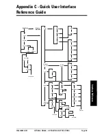
Page 63: ... A392 Type J Type K TypeT TypeT 0 Type E Decimal Point dddd d ddd dd dd ddd d F C Relay 1 Relay 2 Failsafe Delays Scale Sensor break To Program Action Set point Reset point Auto Auto Manual Latch Latch w Clear Pump Alt Off Failsafe 1 Failsafe 2 To Delays To Set point Delay 1 Delay 2 On Off To Program Run Mode Display Max Min Setup Program Password Locked Unlocked TC or RTD Yes No Scale Calibrate T...

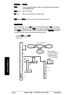
Page 64: ...Run Mode Pressing Enter Ack will disable the 10 second timeout and continuously display Max or Min TC ou RTD Oui Non Transmettre Fonction Débit inhibé Sortie Intensité Linéaire Racine carrée Protocole Adresse Vitesse de transmission Retard de transmission Modbus Time out octet octet Filtre Contournement Série Copie Sélectionner Réglage TC ou RTD Oui Non Diagnostic Etalonnage initial Oui Non Modbus...

Page 65: ...ed for transmitted data Note that in this document hex data is indicated by a 0x prefix ASCII characters are shown with single quotes as in 8 0x38 and ASCII strings are shown with double quotes as in SFT013 To accommodate multiple devices sharing a common serial network RS 485 there is a programmable address code The address code is selected from the front panel or via serial command 38 Note that ...

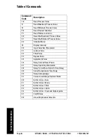
Page 66: ... Process Value 32 Initialize Meter 19 Display Intensity 20 Input Selection Parameters 21 Lockout Code 22 Filter Value 23 Bypass Value 24 Adjustment Value 26 Relay Set and Reset Points 27 Relay Operating Parameters 28 Relay Turn Off and Turn On Time Delay 29 Serial Transmission Time Delay 39 Relay Acknowledge 37 Current and Voltage Decimal Points 40 4 20 mA Out Data 41 4 20 mA Out Mode 42 4 20 mA O...

Page 67: ...ters in the command code and data fields Parity bits are excluded from the calculation Checksum 1 not Command Code high Command Code low any data or arguments 6 ETX 0x03 Terminator character Example Read the set point for Relay 1 of meter 00 Address 00 Command Code 26 Arguments S0 S Set point 0 Relay 1 relay numbering starts with 0 Checksum 1 not 2 6 S 0 1 not 0x32 0x36 0x53 0x30 1 not 0xEB 1 0x14...

Page 68: ...alid messages longer than 22 characters will result in a receive buffer overflow and will not generate a reply Normal operation resumes with the reception of the next start of message character To aid in the development of application software certain syntax errors will result in replies containing special error codes in the command code field Read Only Commands Command STX 0x02 Command Code Comma...

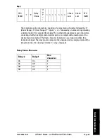
Page 69: ...g is always seven characters consisting of either six digits and a decimal point or six digits with a leading zero if no decimal point is selected The Open character indicates an overrange condition for a temperature input The relay status represents the energized or de energized state of the relay s and is active low logic status 0 relay energized Relay Status Character STX 0x02 1 0 Relay Status ...

Page 70: ... of or followed by a number string The number string is always seven characters consisting of either six digits and a decimal point or six digits with a leading zero if no decimal point is selected Command Code 11 Description Read Maximum Process Value SOH 0x01 Meter Address Meter Address 1 1 9 E ETX 0x03 STX 0x02 1 1 n n n n n n n Check sum Check sum ETX 0x03 Code 12 Description Read Minimum Proc...

Page 71: ...eply data is eight characters consisting of the version code enclosed in quotation marks An example is shown for 01 234 No Data Commands Command Reply STX 0x02 F 0 S F T 0 1 3 3 B ETX 0x03 Code F1 Description Read Firmware Version SOH 0x01 Meter Address Meter Address F 1 8 9 ETX 0x03 STX 0x02 F 1 0 1 2 3 4 9 4 ETX 0x03 Code 30 Description Reset the Maximum Process Value SOH 0x01 Meter Address Mete...

Page 72: ...t value 4 Relay parameters whether installed or not 5 4 20 mA output parameters whether installed or not 6 Serial parameters and address There is no data in the reply Code 31 Description Reset the Minimum Process Value SOH 0x01 Meter Address Meter Address 3 1 9 C ETX 0x03 STX 0x02 3 1 9 C ETX 0x03 Code 32 Description Initialize Meter SOH 0x01 Meter Address Meter Address 3 2 9 B ETX 0x03 STX 0x02 3...

Page 73: ...e and Read Code 19 Description Display Intensity SOH 0x01 Meter Address Meter Address 1 9 9 6 ETX 0x03 SOH 0x01 Meter Address Meter Address 1 9 1 to 8 Check sum Check sum ETX 0x03 STX 0x02 1 9 1 to 8 Check sum Check sum ETX 0x03 Code 20 Description Input Selection Parameters SOH 0x01 Meter Address Meter Address 2 0 9 E ETX 0x03 SOH 0x01 Meter Address Meter Address 2 0 X X X X Check sum Check sum E...

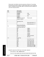
Page 74: ... hex form 0x01 0x30 0x30 0x32 0x30 0x32 0x33 0x38 0x30 0x44 0x31 0x03 Bits Description 15 8 Input Selection 00000000 Volts 00010001 Current 00100010 RTD 00100011 00110010 also valid but 00100011 preferred Thermocouple 7 Temperature Units 0 Display temperature in C 1 Display temperature in F 6 4 Volts or Current Decimal Point Selection ignored for all other input selections 000 dddddd 001 ddddd d 0...

Page 75: ...e 000 and 002 to 199 Note If the input selection is Thermocouple or RTD the decimal point should be selected for 123456 110 except for Type T thermocouple with 0 1 resolution resolution is then set to 12345 6 001 Code 21 Description Lockout Code SOH 0x01 Meter Address Meter Address 2 1 X X X X Check sum Check sum ETX 0x03 STX 0x02 2 1 9 D ETX 0x03 Code 22 Description Filter Value SOH 0x01 Meter Ad...

Page 76: ...implied Command Read Command Write Reply Write and Read Code 23 Description Bypass Value SOH 0x01 Meter Address Meter Address 2 3 9 B ETX 0x03 SOH 0x01 Meter Address Meter Address 2 3 0 0 0 X X X Check sum Check sum ETX 0x03 STX 0x02 2 3 0 0 0 X X X Check sum Check sum ETX 0x03 Code 24 Description Adjustment Value SOH 0x01 Meter Address Meter Address 2 4 9 A ETX 0x03 SOH 0x01 Meter Address Meter A...

Page 77: ...six digits and a decimal point or six digits with a leading zero if no decimal point is selected Note that the write command does not include the decimal point regardless of the decimal point setting Command Read Code 26 Description Relay Set and Reset Points SOH 0x01 Meter Address Meter Address 2 6 S R Relay Check sum Check sum ETX 0x03 SOH 0x01 Meter Address Meter Address 2 6 S R Relay 0 0 X X X...

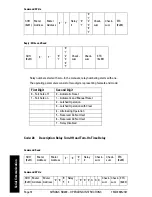
Page 78: ...3 4 7 Check sum Check sum ETX 0x03 SOH 0x01 2 7 0 1 0 1 2 3 4 7 Check sum Check sum ETX 0x03 First Digit Second Digit 0 Fail Safe off 0 Automatic Reset 1 Fail Safe on 1 Automatic and Manual Reset 2 Latched Operation 3 Latched Operation with Clear 4 Alternating Operation 5 Reserved Do Not Use 6 Reserved Do Not Use 7 Relay Disabled Code 28 Description Relay Turn Off and Turn On Time Delay SOH 0x01 M...

Page 79: ... Turn Off Time Delay follow the command code with a 0 Use a 1 for Turn On Time Delay The delay number is 000 followed by the value in seconds The range is 000 to 199 STX 0x02 2 8 0 0 0 X X X Check sum Check sum ETX 0x03 Note Relay numbers start with zero but in the meter instruction manuals relay numbering starts with one ...

Page 80: ...t if a relay is not in a mode that allows acknowledgement it will not be acknowledged Code 29 Description Serial Transmission Time Delay SOH 0x01 Meter Address Meter Address 2 9 9 5 ETX 0x03 SOH 0x01 Meter Address Meter Address 2 9 0 0 0 X X X Check sum Check sum ETX 0x03 STX 0x02 2 9 0 0 0 X X X Check sum Check sum ETX 0x03 Code 39 Description Relay Acknowledge SOH 0x01 Meter Address Meter Addres...

Page 81: ...scription Current and Voltage Decimal Points SOH 0x01 Meter Address Meter Address 3 7 9 6 ETX 0x03 SOH 0x01 Meter Address Meter Address 3 7 Current decimal point Voltage decimal point Check sum Check sum ETX 0x03 STX 0x02 3 7 Current Voltage Check sum Check sum ETX 0x03 Number Decimal Point Position 0 dddddd 1 ddddd d 2 dddd dd 3 ddd ddd 4 dd dddd 5 d ddddd 6 dddddd no decimal CAUTION Starting wit...

Page 82: ...ad Code 40 Description 4 20 mA Output Data SOH 0x01 Meter Address Meter Address 4 0 9 C ETX 0x03 SOH 0x01 Meter Address Meter Address 4 0 0 0 X X X X Check sum Check sum ETX 0x03 STX 0x02 4 0 0 0 X X X X Check sum Check sum ETX 0x03 Note Although the data range is 0 00 to 23 99 mA the actual minimum and maximum outputs available may be different from this range depending on hardware tolerances The...

Page 83: ... to 4 Check sum Check sum ETX 0x03 STX 0x02 4 1 0 8 0 to 4 Check sum Check sum ETX 0x03 First Digit Second Digit 0 No 4 20 mA Output 0 Display Value 8 4 20 mA Output 1 Max Display Value 2 Min Display Value 3 Serial Communication Data in mA 4 Factory Use Only Serial Comm Data in counts Code 42 Description 4 20 mA Output Filter Value SOH 0x01 Meter Address Meter Address 4 2 9 A ETX 0x03 SOH 0x01 Met...

Page 84: ...se values actually represent 0 00 to 23 99 milliamps The decimal point in the write command is implied The following table shows the arguments for the various limit parameters Note Filter Value cannot be accessed through the front panel menu Code 43 Description 4 20 mA Output Limits SOH 0x01 Meter Address Meter Address 4 3 0 to 4 Check sum Check sum ETX 0x03 SOH 0x01 Meter Address Meter Address 4 ...

Page 85: ...r the Display Values will reflect the presently selected decimal point but is fixed 00XX XX for the DAC Output values The following table shows the arguments for the various limit parameters Command Read Code 44 Description 4 20 mA Output Input and Output Points SOH 0x01 Meter Address Meter Address 4 4 0 to 3 Check sum Check sum ETX 0x03 SOH 0x01 Meter Address Meter Address 4 4 0 to 3 0 0 X X X X ...

Page 86: ...nd voltage The reply data format is eight characters consisting of followed by a number string The number string is always seven characters consisting of either six digits and a decimal point or six digits with a leading zero if no decimal point is selected Note that the write command does not include the decimal point regardless of the decimal point setting SOH 0x01 Meter Address Meter Address 4 ...

Page 87: ...ADC_count Gain Offset Exponent DisplayValue ADC_count Input_low 0 5 Gain Offset where Input_low Gain and Offset are user defined either through scaling or external calibration Code 48 Description Linear Exponential Selection SOH 0x01 Meter Address Meter Address 4 8 9 4 ETX 0x03 SOH 0x01 Meter Address Meter Address 4 8 L E Check sum Check sum ETX 0x03 STX 0x02 4 8 L E Check sum Check sum ETX 0x03 ...

Page 88: ...Page 84 SITRANS RD200 OPERATING INSTRUCTIONS 7ML19985JS01 mmmmm Serial Communication Notes ...

Page 89: ...ay status for block reading Initialize Reset Max Min display value Alarm Relay status Relay acknowledge Linear Square Root selection Remote Process scaling initiation 40101 40113 Input selection Decimal points Adjust Bypass Cutoff Filter Lock Baud Parity Modbus Address and Byte to byte timeout Display Intensity 40201 40212 Remote Scaling for Process inputs 40301 40310 Relays Set Reset points Turn ...

Page 90: ...40003 2 0002 Maximum Display value Read Write 1999 to 9999 User defined Integer 03 06 04 Represents the Maximum display value excluding the decimal point since last power up or Max Value reset Decimal point set ting in 40102 Writing any value will reset the Maximum display value to the present display value 40004 3 0003 Minimum Display value Read Write 1999 to 9999 User defined Integer 03 06 04 Re...

Page 91: ...s 06 Clear Relay n alarm condition Set bit equal to 1 to acknowledge Only has effect on relays programmed to allow manual acknowl edging Alm Alarm X don t care 15 14 13 12 11 10 9 8 7 6 5 4 3 2 1 0 X X X X X X Al m 2 Al m1 X X X X X X X X 40014 13 000D Initialize Meter Write Only 0xFF00 to ini tialize None Bit 06 Write 0xFF00 to reinitialize the meter Writing any other data has no effect 40015 14 ...

Page 92: ... of full scale or F Integer 03 06 16 04 Actually represents 0 2 to 99 9 If the input steps greater than the bypass value it will be displayed immediately with no filtering occurring The number represents percent of full scale for pro cess inputs and F for temperature inputs No effect if filter 0 40106 105 0069 Cutoff Read Write 0 to 9999 User Defined Integer 03 06 16 04 Represents the cutoff value...

Page 93: ... saved but don t take effect until next meter reset Modbus command or power up Writing out of range data results in an address of 247 40113 112 0070 Display Intensity Read Write 1 to 8 None Integer 03 06 16 04 8 is the brightest level Writing out of range data results in level 2 brightness 40201 40202 200 00C8 201 00C9 Display 1 2 mA Read Write 1999 to 9999 User Defined Integer 03 06 16 04 Used to...

Page 94: ...10 s of mV 9 99 to 10 00 V 40301 To 40305 300 301 302 303 304 012C to 0130 Relay 1 Set point Reset point Turn on delay Turn off delay Mode Read Write 1999 to 9999 1999 to 9999 0 to 199 0 to 199 Bits 4 2 1 0 User Defined User Defined Seconds Seconds None Integer Integer Integer Integer Word bits 03 06 16 04 Set and Reset points represent the display value without the deci mal point See Relay Config...

Page 95: ... 40405 404 0194 4 20mA out Underrange value Read Write 0 to 2399 10s of A Integer 03 06 16 04 This feature is not available through manual programming Due to hardware variations actual output range is designed to be at least 1 00 to 23 00 mA Writing out of range data results in a value of 3 00 mA 40406 405 0195 4 20mA out Maximum value allowed Read Write 0 to 2399 10s of A Integer 03 06 16 04 This...

Page 96: ...nteger 03 06 16 04 If 4 20mA out mode is set to Serial Comm mA 0x83 this regis ter is in 10 s of A Due to hardware variations the actual output range is at least 1 00 to 23 00 mA Writing out of range data results in a value of 23 99 mA If 4 20mA out mode is set to Serial Comm bits 0x84 this regis ter is in DAC bits See 4 20 mA Output Modes on page 97 49101 To 49104 9100 9103 238C 238F Product Iden...

Page 97: ...s are noted in the comments 3 Data Types Data format is highest byte first Word 16 bit Integer 32768 to 32767 Long 2 147 483 648 to 2 147 483 647 Float IEEE floating point format 4 bytes Decimal point setting in 40102 These values represent the number without regard to the decimal point The decimal point setting can be found in Holding Register 40102 For example if the number 12 34 is displayed a ...

Page 98: ... reply will be 0x0000 An unlocked meter can be locked by writing any non zero value but the value must be in BCD i e only nybbles between 0 and 9 If a nybble between A and F is sent no change to lock status will occur and the return value will be 0xFF00 6 Modbus is a Registered Trademark of Schneider Automation Inc WARNING The scaling process takes the input values in mA or volts and converts them...

Page 99: ...the input selected for example if RTD is selected thermocouple type selection is not allowed and decimal point is forced to none Bit s 15 14 13 12 11 10 9 8 7 6 5 4 3 2 1 0 Function F or C Active decimal point setting Temperature sensor type Input selected 0 C 0x1000 123 4 0x0000 J 0x0000 Volts 1 F 0x2000 12 34 0x0100 K 0x0011 mA 0x3000 1 234 0x0200 T 0x0022 RTD 0x6000 1234 0x0300 T 0 1 0x0023 TC ...

Page 100: ...the decimal point setting in bits 14 to 12 of 40101 will be the same as the one in bits 3 to 0 of 40103 If a temperature input is selected the settings in 40103 may or may not be the same as the active setting in 40101 There is no storage for the decimal point settings for the RTD or thermocouple inputs because these are fixed Relay Configuration Bit s 15 8 7 4 3 0 Function 00000000 Decimal Point ...

Page 101: ...version 3 xxx Bit s 15 8 7 6 3 2 0 Function 00000000 Output Option 000 0 4 20 mA Data Source 0 Relays 4 Serial Comm bits The data for the 4 20 mA output is register 40412 1 4 20 mA 5 Unused 6 Unused 7 Unused RD200 Version 3 xxx 40001 to 40016 40101 to 40113 40201 to 40212 40301 to 40310 40401 to 40412 49101 to 49116 ...

Page 102: ...Page 98 SITRANS RD200 OPERATING INSTRUCTIONS 7ML19985JS01 mmmmm Modbus Register Notes ...

Page 103: ...rature input 6 Installation information 9 panel mounting instructions 9 unpacking 9 L LED status indicators 17 M Menus advanced features 41 analog output Aout 33 calibration CAL 36 decimal point dEc P 23 diagnostics diAG 51 display intensity intY 46 input signal inPt 21 internal calibration ICAL 38 linear or square root function Func 45 low flow cutoff cut F 45 main 20 meter copy CoPY 47 noise fil...

Page 104: ...bus protocol 85 PDC protocol 61 setup 5 software 5 Setup decimal point 23 fail safe operation 25 input signal 21 main menu 20 numeric values 20 quick user interface 59 relay and alarm operation 27 relay operation 24 scaling output 33 sensor break 34 temperature scale 23 time delay 26 Signal Connections current and voltage 12 thermocouple and RTD 13 SITRANS RD Software determining version 51 inform...

Page 105: ......

Page 106: ...emens com level For more information www siemens com processautomation Siemens AG Industry Sector 1954 Technology Drive P O Box 4225 Peterborough ON Canada K9J 7B1 Subject to change without prior notice 7ML19985JS01 Rev 1 3 email techpubs smpi siemens com Siemens AG 2012 7ml19985JS01 ...

Reviews: