background image

Safety notes

2

2.1

Prerequisites for safe use

This device left the factory in good working condition. In order to maintain this status and to 

ensure safe operation of the device, observe these instructions and all the specifications 

relevant to safety.
Observe the information and symbols on the device. Do not remove any information or symbols 

from the device. Always keep the information and symbols in a completely legible state.

2.1.1

Warning symbols on the device

Symbol

Explanation
Consult operating instructions

2.1.2

Laws and directives

Observe the safety rules, provisions and laws applicable in your country during connection, 

assembly and operation. These include, for example:     
● National Electrical Code (NEC - NFPA 70) (USA)
● Canadian Electrical Code (CEC) (Canada)
Further provisions for hazardous area applications are for example:   
● IEC 60079-14 (international)
● EN 60079-14 (EU)

2.1.3

Conformity with European directives

The CE mark on the device is a sign of conformity with the following European directives:

Electromagnetic compatibili‐

ty EMC 

2014/30/EU

Directive of the European Parliament and of the Council on the 

harmonization of the laws of the Member States relating to elec‐

tromagnetic compatibility

Atmosphère explosible 

ATEX 

2014/34/EU

Directive of the European Parliament and of the Council on the 

harmonization of the laws of the Member States relating to equip‐

ment and protective systems intended for use in potentially ex‐

plosive atmospheres

SITRANS TH320/TH420/TR320/TR420/TF320/TF420

Compact Operating Instructions, 03/2018, A5E41865021-AA

15

Summary of Contents for SITRANS Series

Page 1: ...S TH320 TH420 TR320 TR420 TF320 TF420 Compact Operating Instructions 03 2018 A5E41865021 AA Introduction 1 Safety notes 2 Installing mounting 3 Connecting 4 Commissioning 5 Service and maintenance 6 Technical specifications 7 Appendix A A ...

Page 2: ...se who based on their training and experience are capable of identifying risks and avoiding potential hazards when working with these products systems Proper use of Siemens products Note the following WARNING Siemens products may only be used for the applications described in the catalog and in the relevant technical documentation If products and components from other manufacturers are used these ...

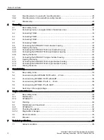
Page 3: ... Use in hazardous areas 16 3 Installing mounting 19 3 1 Basic safety notes 19 3 1 1 ATEX IECEx and others 19 3 1 1 1 Safety information for installation in Intrinsic safety ia ib 19 3 1 1 2 Safety information for installation in Non sparking nA ec and Intrinsic safety ic 20 3 1 2 CSA FM 21 3 1 2 1 Safety information for installation in Intrinsic safety ia 21 3 1 2 2 Safety information for installa...

Page 4: ... Connecting the SITRANS TF320 single chamber housing 46 4 7 3 Connecting the SITRANS TF420 single chamber housing 48 4 7 4 Closing the device 51 5 Commissioning 53 5 1 Basic safety notes 53 5 2 Commissioning the SITRANS TH TR with 4 20 mA 53 5 3 Commissioning SITRANS TH TR with HART 54 5 4 Commissioning SITRANS TF with 4 20 mA 55 5 5 Commissioning SITRANS TF with HART 56 5 6 Switching on the suppl...

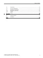
Page 5: ...and approvals 67 7 4 1 ATEX IECEx and related 67 7 4 2 FM CSA 72 7 5 Display 75 A Appendix A 77 A 1 Technical support 77 A 2 Certificates 77 Index 79 Table of contents SITRANS TH320 TH420 TR320 TR420 TF320 TF420 Compact Operating Instructions 03 2018 A5E41865021 AA 5 ...

Page 6: ...Table of contents SITRANS TH320 TH420 TR320 TR420 TF320 TF420 6 Compact Operating Instructions 03 2018 A5E41865021 AA ...

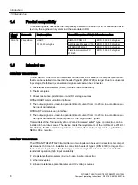
Page 7: ...lize optimum performance from the device read the complete operating instructions 1 2 Document history The following table contains the major changes in the documentation compared to the previous edition Edition Comment 03 2018 First edition 1 3 Scope of validity of this document Article no Product 7NG031 TH320 mA HART 7NG041 TH420 mA HART 7NG032 TR320 mA 7NG042 TR420 mA HART 7NG034 TF320 single c...

Page 8: ...s a load independent direct current from 4 to 20 mA in accordance with the input characteristic With HART communication interface The output signal is a load independent direct current from 4 to 20 mA in accordance with the input characteristic superimposed by the digital HART signal Transmitters of the intrinsically safe or Zone 2 increased safety type of protection can be installed in hazardous ...

Page 9: ... sensor signals into a load independent DC signal according to the sensor characteristic The following sensors and signal sources can be connected to the input block Resistance thermometer Thermocouples Resistance based sensor potentiometer DC voltage sources The output signal is a load independent direct current from 4 to 20 mA in accordance with the input characteristic superimposed by the digit...

Page 10: ...ting authority Serial number Device version Product name Manufacturer Figure 1 1 Example of nameplate for SITRANS TH with approval information 3 1 6 61 2 9 6 5 3725 8 7 855 17 7 6 7 5 1 P 0 66 Article number QR code for mobile website with device specific information about the product Figure 1 2 Example of nameplate on the base of the SITRANS TH with general information Introduction 1 6 Nameplate ...

Page 11: ...D number of the named testing authority QR code for mobile website with device spe cific information about the product Device version Conformity with country specific guidelines Serial number Read the compact operating instructions Ex marking Manufacturer s address Article number Place of manufacture Product name Figure 1 3 Example of nameplate for SITRANS TR with approval information Introduction...

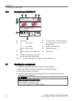
Page 12: ...4 UB DC 13 1 32V lo 4 20mA HART IP66 68 Siemens AG DE 76181 Karlsruhe Made in France Manufacturer Conformity with country specific guidelines S Serial number CE marking with ID number of the named testing authority 1P Article number Marking for hazardous area DEVICE NO Device version Place of manufacture Observe the compact operating instruc tions Product name QR code for mobile website with devic...

Page 13: ...e applied as soon as they are available and that the latest product versions are used Use of product versions that are no longer supported and failure to apply the latest updates may increase customer s exposure to cyber threats To stay informed about product updates subscribe to the Siemens Industrial Security RSS Feed under https www siemens com industrialsecurity 1 9 Transportation and storage ...

Page 14: ...y applicable warranty conditions Any statements regarding device versions described in the manual do not create new warranties or modify the existing warranty The content reflects the technical status at the time of publishing Siemens reserves the right to make technical changes in the course of further development Introduction 1 10 Notes on warranty SITRANS TH320 TH420 TR320 TR420 TF320 TF420 14 ...

Page 15: ...xample National Electrical Code NEC NFPA 70 USA Canadian Electrical Code CEC Canada Further provisions for hazardous area applications are for example IEC 60079 14 international EN 60079 14 EU 2 1 3 Conformity with European directives The CE mark on the device is a sign of conformity with the following European directives Electromagnetic compatibili ty EMC 2014 30 EU Directive of the European Parl...

Page 16: ...nditions We highly recommend that you contact your Siemens representative or our application department before you operate the device under special ambient conditions as can be encountered in nuclear power plants or when the device is used for research and development purposes 2 3 Use in hazardous areas Qualified personnel for hazardous area applications Persons who install connect commission oper...

Page 17: ... in Technical specifications Page 65 WARNING Use of incorrect device parts in potentially explosive environments Devices and their associated device parts are either approved for different types of protection or they do not have explosion protection There is a risk of explosion if device parts such as covers are used for devices with explosion protection that are not expressly suited for this type...

Page 18: ...Safety notes 2 3 Use in hazardous areas SITRANS TH320 TH420 TR320 TR420 TF320 TF420 18 Compact Operating Instructions 03 2018 A5E41865021 AA ...

Page 19: ...ety afterwards Note the following instructions for installation in a hazardous gas atmosphere The temperature transmitter must be installed in an enclosure of form B in accordance with DIN 43729 or equivalent so that at least IP20 protection in accordance with IEC EN 60529 is guaranteed The enclosure must be suitable for the application and installed to meet the applicable regulations Note the fol...

Page 20: ...east IP20 according to IEC EN 60529 that is suitable for the application and is correctly installed For Ex nA and Ex ec the transmitter must be installed in an enclosure providing a degree of protection of at least IP54 in accordance with IEC EN 60079 0 In addition the enclosure shall provide an internal pollution degree 2 or better as defined in IEC EN 60664 1 Cable entry devices and blanking ele...

Page 21: ...greater than the voltage Uo or Voc or Vt and current Io or Isc or It and the power Po which can be delivered by the barrier The sum of the maximum unprotected capacitance Ci for each intrinsically device and the interconnect ing wiring must be less than the capacitance Ca which can be safely connected to the barrier The sum of the maximum unprotected inductance Li for each intrinsically device and...

Page 22: ...eld Wiring Circuit concept allows interconnection of Nonincendive Field wiring Apparatus with Associated Nonincendive Field Wiring Apparatus or Assosicated Intrinsically Safe Apparatus or Associated Apparatus not specially examined in combination as a syatem using any of the wiring methods permitted for unclassified locations Voc Vmax Ca Ci Ccable La Li Lcable 3 1 3 SITRANS TF 3 1 3 1 Unsuitable c...

Page 23: ...ither secured in the base of the connection head or in the raised cover of the connection head The scope of the delivery of the transmitter includes Springs Fixing screws Lock washers for installation on the round plate SITRANS TH Fastening the transmitter In the cover of the connection head In the base of the connection head Transmitter Ceramic base of the measuring element Connection head Instal...

Page 24: ...the scope of delivery for the transmitter are not required for the installation on DIN rails or G rails You can either install the transmitter on a 35 mm DIN rail or on a 32 mm G rail DIN EN 60715 applies to DIN rails and G rails in this context The DIN G rail adapter required for installation can be ordered as an accessory under the Order No 7NG3092 8KA Adhere to the ambient conditions specified ...

Page 25: ...0715 Comply with the ambient conditions specified in the technical data 3 5 Mounting the SITRANS TF single chamber housing Introduction The mounting holes in the bracket and the device enclosure determine the permitted mounting positions Installing mounting 3 5 Mounting the SITRANS TF single chamber housing SITRANS TH320 TH420 TR320 TR420 TF320 TF420 Compact Operating Instructions 03 2018 A5E41865...

Page 26: ...e 2 Fasten the bracket to the pipe clamp or wall 3 6 Mounting the SITRANS TF dual chamber housing 3 6 1 Mounting device to a pole with mounting bracket Introduction The mounting holes in the bracket and the device enclosure determine the permitted mounting positions Installing mounting 3 6 Mounting the SITRANS TF dual chamber housing SITRANS TH320 TH420 TR320 TR420 TF320 TF420 26 Compact Operating...

Page 27: ...bracket 2 Secure the enclosure with the fixing screws and washers onto the mounting bracket 3 Secure the mounting bracket with pole clamp washers and nuts on the pole 3 6 2 Mounting device to the wall with mounting bracket Introduction The mounting holes in the bracket and the device enclosure determine the permitted mounting positions Installing mounting 3 6 Mounting the SITRANS TF dual chamber h...

Page 28: ... wall with mounting bracket 1 Push the enclosure onto the mounting bracket 2 Secure the enclosure with the fixing screws and washers onto the mounting bracket 3 Secure the mounting bracket to the wall Use suitable fixing screws Installing mounting 3 6 Mounting the SITRANS TF dual chamber housing SITRANS TH320 TH420 TR320 TR420 TF320 TF420 28 Compact Operating Instructions 03 2018 A5E41865021 AA ...

Page 29: ...e that you have switched off all physical variables such as pressure temperature electricity etc or that they have a harmless value If the device contains hazardous media it must be emptied prior to disassembly Make sure that no environmentally hazardous media are released Secure the remaining connections so that no damage can result if the process is started unintentionally Installing mounting 3 ...

Page 30: ...Installing mounting 3 7 Disassembly SITRANS TH320 TH420 TR320 TR420 TF320 TF420 30 Compact Operating Instructions 03 2018 A5E41865021 AA ...

Page 31: ...at the cables are seated firmly WARNING Improper power supply Risk of explosion in hazardous areas as result of incorrect power supply e g using direct current instead of alternating current Connect the device in accordance with the specified power supply and signal circuits The relevant specifications can be found in the certificates in Technical specifications Page 65 or on the nameplate NOTICE ...

Page 32: ...sparking nA ec Zone 2 are regulated in the relevant certificate Note Improvement of interference immunity Lay signal cables separate from cables with voltages 60 V Use cables with twisted wires Keep device and cables at a distance from strong electromagnetic fields Take account of the conditions for communication specified in the Technical specifications Page 65 Use shielded cables to guarantee th...

Page 33: ...put single pole or two pole 3 wire or 4 wire potentiometer 2 Connect the supply voltage to the terminals 1 and 2 Take the polarity into account The device has reverse polarity protection 7 67 E X T TEST 5 57 For devices with HART communication connect a 250 Ω resistor Connecting 4 2 Connecting TH320 SITRANS TH320 TH420 TR320 TR420 TF320 TF420 Compact Operating Instructions 03 2018 A5E41865021 AA 3...

Page 34: ...t 2 wire or 3 wire CJC Input 2 2 wire 3 wire or 4 wire RTD Input 1 I1 and or input 2 I2 3 wire or 4 wire potentiometer Input 1 I1 5 wire potentiome ter Input 2 I2 3 wire potentiome ter 2 Connect the supply voltage to the terminals 1 and 2 Take the polarity into account The device has reverse polarity protection 7 67 E X T TEST 5 57 For devices with HART communication connect a 250 Ω resistor Conne...

Page 35: ...wire 3 wire or 4 wire RTD or wire resistance I1 Input 1 TC internal CJC or external 2 wire or 3 wire CJC Voltage input single pole or two pole 3 wire or 4 wire potentiometer 2 Connect the supply voltage to the terminals 3 and 4 Connecting 4 4 Connecting TR320 SITRANS TH320 TH420 TR320 TR420 TF320 TF420 Compact Operating Instructions 03 2018 A5E41865021 AA 35 ...

Page 36: ...tion connect a 250 Ω resistor 3 Take the polarity into account The device has reverse polarity protection Connecting 4 4 Connecting TR320 SITRANS TH320 TH420 TR320 TR420 TF320 TF420 36 Compact Operating Instructions 03 2018 A5E41865021 AA ...

Page 37: ... ensure intrinsic safety Input 1 I1 and or input 2 I2 2 wire 3 wire or 4 wire RTD or linear resistance Input 1 and or input 2 TC int CJC or ext 2 wire or 3 wire CJC Voltage input single pole or two pole Connecting 4 5 Connecting TR420 SITRANS TH320 TH420 TR320 TR420 TF320 TF420 Compact Operating Instructions 03 2018 A5E41865021 AA 37 ...

Page 38: ...iome ter Input 2 I2 3 wire potentiome ter 2 Connect the supply voltage to the terminals 3 and 4 5 57 For devices with HART communication connect a 250 Ω resistor 3 Take the polarity into account The device has reverse polarity protection Connecting 4 5 Connecting TR420 SITRANS TH320 TH420 TR320 TR420 TF320 TF420 38 Compact Operating Instructions 03 2018 A5E41865021 AA ...

Page 39: ...t Safety catch back Figure 4 1 Rear view of the device 1 Use a 3 mm Allen key to loosen the safety catch back 2 Unscrew the cover of the electrical cable compartment Connecting 4 6 Connecting the SITRANS TF dual chamber housing SITRANS TH320 TH420 TR320 TR420 TF320 TF420 Compact Operating Instructions 03 2018 A5E41865021 AA 39 ...

Page 40: ... device to the plant with the protective conductor connection 3 Connect the wires of the power supply to the terminals and Take the polarity into account The device has reverse polarity protection 4 Connect the shield to the screw of the ground terminal The screw of the ground terminal is electrically connected to the external protective conductor connection Connecting 4 6 Connecting the SITRANS T...

Page 41: ...ct the input terminals 2 wire 3 wire or 4 wire RTD or linear resistance I1 Input 1 TC internal CJC or external 2 wire or 3 wire CJC 6 Voltage input single pole or two pole 3 wire or 4 wire potentiometer Connecting 4 6 Connecting the SITRANS TF dual chamber housing SITRANS TH320 TH420 TR320 TR420 TF320 TF420 Compact Operating Instructions 03 2018 A5E41865021 AA 41 ...

Page 42: ... device to the plant with the protective conductor connection 3 Connect the wires of the power supply to the terminals and Take the polarity into account The device has reverse polarity protection 4 Connect the shield to the screw of the ground terminal The screw of the ground terminal is electrically connected to the external protective conductor connection Connecting 4 6 Connecting the SITRANS T...

Page 43: ... 2 I2 TC int CJC or ext 2 wire 3 wire or 4 wire CJC Input 1 I1 and or input 2 I2 Voltage input single pole or two pole Input 1 TC int CJC or ext 2 wire or 3 wire CJC Input 2 2 wire 3 wire or 4 wire RTD Input 1 I1 and or input 2 I2 3 wire or 4 wire potentiometer Input 1 I1 5 wire potentiome ter Input 2 I2 3 wire potentiome ter Connecting 4 6 Connecting the SITRANS TF dual chamber housing SITRANS TH...

Page 44: ...ey will go 2 Secure both covers with the safety catch or 3 Close the cover over the buttons 4 Tighten the screw for the cover over the buttons 5 Check the tightness of the cable glands and in accordance with the degree of protection Connecting 4 6 Connecting the SITRANS TF dual chamber housing SITRANS TH320 TH420 TR320 TR420 TF320 TF420 44 Compact Operating Instructions 03 2018 A5E41865021 AA ...

Page 45: ...ety catch Figure 4 5 Opening device with single chamber housing 1 Use a 3 mm Allen key to loosen the safety catch 2 Unscrew the cover of the electrical cable compartment Connecting 4 7 Connecting the SITRANS TF single chamber housing SITRANS TH320 TH420 TR320 TR420 TF320 TF420 Compact Operating Instructions 03 2018 A5E41865021 AA 45 ...

Page 46: ...r 2 Loosen the fastening screws of the temperature transmitter and remove it 3 Lead the shielded connecting cables through the cable glands Connecting 4 7 Connecting the SITRANS TF single chamber housing SITRANS TH320 TH420 TR320 TR420 TF320 TF420 46 Compact Operating Instructions 03 2018 A5E41865021 AA ...

Page 47: ...erminals and output terminals Connecting TH320 Page 33 5 57 HART communication resistor optional 7 For devices with Intrinsic safety type of protection use an isolating power supply that corresponds to the requirements of the relevant type of protection 8 Insert the display Connecting 4 7 Connecting the SITRANS TF single chamber housing SITRANS TH320 TH420 TR320 TR420 TF320 TF420 Compact Operating...

Page 48: ...ecting the SITRANS TF420 single chamber housing Procedure 1 Remove the display from the holder 2 Loosen the fastening screws of the temperature transmitter and remove it Connecting 4 7 Connecting the SITRANS TF single chamber housing SITRANS TH320 TH420 TR320 TR420 TF320 TF420 48 Compact Operating Instructions 03 2018 A5E41865021 AA ...

Page 49: ...he screw of the ground terminal is electrically connected to the external protective conductor connection 5 Insert the temperature transmitter and screw it in Connecting 4 7 Connecting the SITRANS TF single chamber housing SITRANS TH320 TH420 TR320 TR420 TF320 TF420 Compact Operating Instructions 03 2018 A5E41865021 AA 49 ...

Page 50: ...ting power supply that corresponds to the requirements of the relevant type of protection 8 Insert the display 9 Screw the cover back on as far as it will go 10 Connect the device to the plant with the protective conductor connection Connecting 4 7 Connecting the SITRANS TF single chamber housing SITRANS TH320 TH420 TR320 TR420 TF320 TF420 50 Compact Operating Instructions 03 2018 A5E41865021 AA ...

Page 51: ...ck on as far as it will go 2 Use a 3 mm Allen key to secure the cover with the safety catch 3 Check the tightness of the cable glands in accordance with the degree of protection Connecting 4 7 Connecting the SITRANS TF single chamber housing SITRANS TH320 TH420 TR320 TR420 TF320 TF420 Compact Operating Instructions 03 2018 A5E41865021 AA 51 ...

Page 52: ...Connecting 4 7 Connecting the SITRANS TF single chamber housing SITRANS TH320 TH420 TR320 TR420 TF320 TF420 52 Compact Operating Instructions 03 2018 A5E41865021 AA ...

Page 53: ...s no longer guaranteed Check the gravity of the error Correct the error If the error still exists Take the device out of operation Prevent renewed commissioning 5 2 Commissioning the SITRANS TH TR with 4 20 mA Introduction In this section you will learn how to commission the device step by step Before you start please read the following safety notes General safety notes Page 15 Basic safety notes ...

Page 54: ...ltage Page 57 5 Wait for 2 seconds After this start up time the device is operational 6 Wait 5 minutes to get exact measured values Result The LED is lit green 5 3 Commissioning SITRANS TH TR with HART Introduction In this section you will learn how to commission the device step by step Before you start please read the following safety notes General safety notes Page 15 Basic safety notes Installi...

Page 55: ...device step by step Before you start please read the following safety notes General safety notes Page 15 Basic safety notes Installing mounting Page 19 Basic safety notes Connecting Page 31 Basic safety notes Commissioning Page 53 Read the entire device manual in order to achieve the optimum performance of the device Procedure 1 If you want to change the factory settings configure the device using...

Page 56: ...ocedure 1 Mount the device Mounting the SITRANS TF single chamber housing Page 25 Mounting the SITRANS TF dual chamber housing Page 26 2 Connect the device Connecting the SITRANS TF single chamber housing Page 45 Mounting the SITRANS TF dual chamber housing Page 26 3 Switch on the power supply Switching on the supply voltage Page 57 4 Wait for 2 seconds After this start up time the device is opera...

Page 57: ...ar briefly on the display The measured values are shown on the display For a device without a display you read off the current output as follows Over the remote control e g SIMATIC PDM With a DC current measuring device AUTOHOTSPOT Result The device is now ready for operation Commissioning 5 6 Switching on the supply voltage SITRANS TH320 TH420 TR320 TR420 TF320 TF420 Compact Operating Instruction...

Page 58: ...Commissioning 5 6 Switching on the supply voltage SITRANS TH320 TH420 TR320 TR420 TF320 TF420 58 Compact Operating Instructions 03 2018 A5E41865021 AA ...

Page 59: ...ower supply lightning protection and grounds 6 1 2 SITRANS TF Note The device is maintenance free WARNING Use of a computer in a hazardous area If the interface to the computer is used in the hazardous area there is a risk of explosion Ensure that the atmosphere is explosion free hot work permit WARNING Dust layers above 5 mm Risk of explosion in hazardous areas Device may overheat due to dust bui...

Page 60: ... enclosure with the inscriptions and the display window using a cloth moistened with water or a mild detergent Do not use any aggressive cleansing agents or solvents e g acetone Plastic parts or the painted surface could be damaged The inscriptions could become unreadable See also Cleaning Page 60 WARNING Electrostatic charge Risk of explosion in hazardous areas if electrostatic charges develop fo...

Page 61: ...or the device or enclosed with the accessory or spare part WARNING Improper connection after maintenance Risk of explosion in areas subject to explosion hazard Connect the device correctly after maintenance Close the device after maintenance work Refer to Connecting Page 31 6 3 1 SITRANS TF WARNING Impermissible repair and maintenance of the device Repair and maintenance must be carried out by Sie...

Page 62: ... wrong seals with flush mounted process connections can cause measuring errors and or damage the diaphragm Always use seals which comply with the process connection standards or are recommended by Siemens 1 Clean the enclosure and seals 2 Check the enclosure and seals for cracks and damage 3 Grease the seals if necessary or 4 Replace the seals 6 3 1 2 Diagnostics messages Device diagnostics e g se...

Page 63: ...re that all hollow areas are free from hazardous substances Check the item after it has been cleaned Any devices replacement parts returned without a decontamination declaration will be cleaned at your expense before further processing 6 5 Disposal Devices described in this manual should be recycled They may not be disposed of in the municipal waste disposal services according to the Di rective 20...

Page 64: ...Service and maintenance 6 5 Disposal SITRANS TH320 TH420 TR320 TR420 TF320 TF420 64 Compact Operating Instructions 03 2018 A5E41865021 AA ...

Page 65: ...inals Transmitter enclosure IP68 IP20 IP66 IP67 IP68 Terminal IP00 IP20 IP00 7 2 Construction Mechanical specifications SITRANS TH SITRANS TR SITRANS TF Weight 50 g 122 g 0 27 lb Single chamber hous ing 0 85 kg Dual chamber housing Aluminum 1 3 kg stainless steel 3 3 kg Maximum wire thickness 1 x 1 5 mm2 stranded wire 2 5 mm2 AWG 13 Screw terminals tightening torque 0 4 Nm 0 5 0 6 Nm Vibration IEC...

Page 66: ... software Warming up time 5 min Starting time 2 75 s Programming SIPROM T or HART Signal to noise ratio 60 dB Long term stability better than 0 05 of measuring span year 0 18 of measuring span 5 years Response time 4 to 20 mA 55 ms HART 75 ms typically 70 ms Programmable attenuation 0 to 6 s Signal dynamic input 24 bit Signal dynamic output 18 bit Influence of changes in supply voltage 0 005 of me...

Page 67: ...BR IEC60079 15 2012 ABNT NBR IEC60079 7 2013 DEK 17 00xxX DEK xx 00xxX DEK xx 00xxU ГОСТ 31610 0 2014 IEC 60079 0 2011 ГОСТ 31610 7 2012 IEC 60079 7 2006 ГОСТ 31610 11 2014 IEC 60079 11 2011 ГОСТ 31610 15 2014 IEC 60079 15 2010 TC RU C DE xxxx x xxxxx ОС НАНИО ЦСВЭ TC RU C DE xxxx x xxxxx ОС НАНИО ЦСВЭ EN 60079 0 2012 A11 2013 EN 60079 1 2014 EN 60079 31 2014 DEKRA xx ATEX xxxx X IEC60079 0 2017 I...

Page 68: ...C 58 149 F temperature class T5 50 50 C 58 122 F temperature class T6 50 85 C 58 185 F temperature class T4 50 65 C 58 149 F temperature class T5 50 50 C 58 122 F temperature class T6 50 85 C 58 185 F temperature class T4 50 65 C 58 149 F temperature class T5 50 50 C 58 122 F temperature class T6 Permissible ambient temperature Pi 750 mW 50 85 C 58 185 F temperature class T4 50 70 C 58 158 F tempe...

Page 69: ...perature class T4 50 70 C 58 158 F temperature class T5 50 55 C 58 131 F temperature class T6 50 85 C 58 185 F temperature class T4 50 70 C 58 158 F temperature class T5 50 55 C 58 131 F temperature class T6 50 85 C 58 185 F temperature class T4 50 70 C 58 158 F temperature class T5 50 55 C 58 131 F temperature class T6 Output terminals SITRANS TH SI TRANS TF single chamber housing 1 2 SITRANS TR ...

Page 70: ...50 85 C 58 185 F temperature class T4 50 70 C 58 158 F temperature class T5 50 55 C 58 131 F temperature class T6 Output terminals SITRANS TH SI TRANS TF single chamber housing 1 2 SITRANS TR 3 4 SITRANS TF dual chamber housing and Umax 30 V DC Permissible ambient temperature 50 85 C 58 185 F temperature class T4 50 75 C 58 167 F temperature class T5 50 60 C 58 140 F temperature class T6 Input ter...

Page 71: ...d Umax 30 V DC Imax 23 mA Permissible ambient temperature 50 85 C 58 185 F temperature class T4 50 75 C 58 167 F temperature class T5 50 60 C 58 140 F temperature class T6 Input terminals SITRANS TF 3 4 5 6 7 8 9 SITRANS TR 5 6 7 8 9 10 11 12 Uo 7 2 V DC Io 12 9 mA Po 23 3 mW Lo 200 mH Co 13 5 μF Technical specifications 7 4 Certificates and approvals SITRANS TH320 TH420 TR320 TR420 TF320 TF420 Co...

Page 72: ...ass 3810 2005 ANSI ISA 60079 0 2009 ANSI ISA 60079 11 2009 ANSI ISA 60079 15 2009 FMxxCAxxxx FMxxUSxxxx CSA c CSA Std C22 2 No 157 92 R2012 CAN CSA C22 2 No 60079 0 11 CAN CSA C22 2 No 60079 11 11 CAN CSA C22 2 No 60079 15 12 CSA 61010 1 12 CSA us UL Std No 913 Ed 8 UL 60079 0 Ed 5 UL 60079 11 Ed 6 UL 60079 15 Ed 4 UL 61010 1 Ed 3 CSA 1861385 Intrinsic safety ia type of protection Technical specif...

Page 73: ...tput terminals SITRANS TH SI TRANS TF single chamber housing 1 2 SITRANS TR 3 4 SITRANS TF dual chamber housing and Ui 30 V DC Ii 100 mA Pi 750 mW Li 0 μH Ci 1 0 nF Permissible ambient temperature 50 85 C 58 185 F temperature class T4 50 75 C 58 167 F temperature class T5 50 60 C 58 140 F temperature class T6 Input terminals SITRANS TH TF 3 4 5 5 7 8 9 SITRANS TR 5 6 7 8 9 10 11 12 Uo 7 2 V DC Io ...

Page 74: ...hat the supply voltage including transients does not rise above 140 of the rated voltage Name NI CL I Div 2 GP ABCD T6 T4 Ex nA IIC T6 T4 Gc AEx nA IIC T6 T4 Gc Output terminals SITRANS TH SI TRANS TF single chamber housing 1 2 SITRANS TR 3 4 SITRANS TF dual chamber housing and Umax 37 V DC Permissible ambient temperature 50 85 C 58 185 F temperature class T4 50 70 C 58 158 F temperature class T5 ...

Page 75: ...e range 25 85 C 13 185 F You can find the data for use in hazardous areas in the respective certificate Operating and storage temperature range 40 85 C 40 185 F You can find the data for use in hazardous areas in the respective certificate Best readability 10 70 C 14 158 F Power supply Power supply From two wire line with loop current 4 20 mA Own power consumption 3 mA Voltage drop over terminals ...

Page 76: ...IN EN 61326 1 and NAMUR recom mendation NE21 Construction Dimensions Diameter 64 3 mm 2 53 Height 15 22 5 mm 0 6 0 88 Installation Plug in Enclosure material Plastic Wiring Plug in connection Technical specifications 7 5 Display SITRANS TH320 TH420 TR320 TR420 TF320 TF420 76 Compact Operating Instructions 03 2018 A5E41865021 AA ...

Page 77: ...pport Personal contact If you have additional questions about the device please contact your Siemens personal contact at Partner http www automation siemens com partner To find the personal contact for your product go to All Products and Branches and select Products Services Industrial Automation Process Instrumentation Documentation You can find documentation on various products and systems at In...

Page 78: ...Appendix A A 2 Certificates SITRANS TH320 TH420 TR320 TR420 TF320 TF420 78 Compact Operating Instructions 03 2018 A5E41865021 AA ...

Page 79: ... Disassembly 15 Personell 15 M Maintenance 59 Manuals 77 Modifications correct usage 16 improper 16 O Operating Instructions 77 P Potentiometers 9 Product name 12 Q QR code 12 Qualified personnel 16 R Resistance thermometer 9 Resistance based sensor 9 Return procedure 63 S Scope of delivery 12 Serial number 12 Service 77 Service Support 77 Internet 77 Support 77 Support request 77 T Technical Supp...

Page 80: ...Index SITRANS TH320 TH420 TR320 TR420 TF320 TF420 80 Compact Operating Instructions 03 2018 A5E41865021 AA ...

Reviews: