Configuration
6.2 Configuring the busbar run layout
SIVACON 8PS - Configuring with LX system
Configuration Manual, 10/2011, A5E02194899-02
119
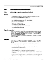
6.2.3
Configuring vertical busbar runs
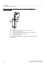
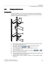
Mounting position
The vertical installation position of the busbar runs is fixed due to the limited permissible
installation position of the overload and short-circuit protection elements in the tap-off unit,
and the ease of installation of the trunking units.
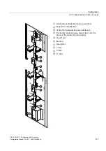
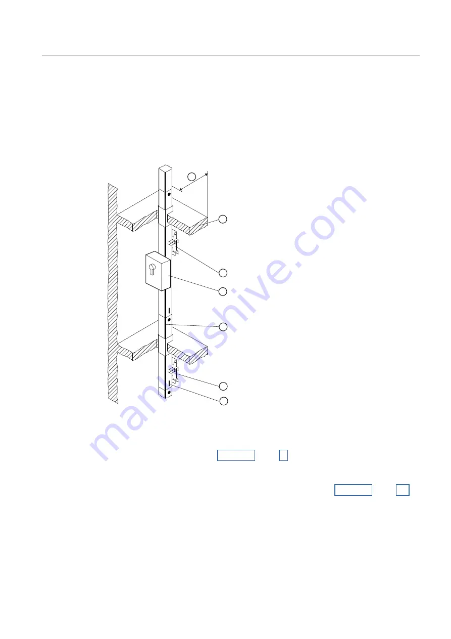
①
Compensate for uneven walls using material on site. The minimum distance dictated
by the vertical fixing bracket is 6 cm.
②
Here: Centre of fire barrier = centre of fire barrier ceiling (tolerance range for
positioning, see fire barrier Fire barrier (Page 73))
③
1 or 2 vertical fixing brackets per storey (storey height 3.40 m to 3.90 m).
Please note: Min./max. load
④
Tap-off unit (positioning of the tap-off point for fire barrier, see Fire barrier (Page 106))
⑤
PEN (L3, N or PE)
1)
always on the right
⑥
The end of trunking unit without joint block always points downwards. Tightening of the
joint block always on the side with phase L1.
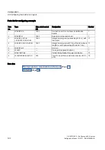
1)
Depending on the conductor configuration, the PEN, L3, N or PE conductor is always
on the right.

